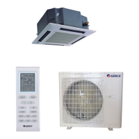
Do you have a question about the Gree GKH(24)BA-K3DNA1A/I and is the answer not in the manual?
| Brand | Gree |
|---|---|
| Model | GKH(24)BA-K3DNA1A/I |
| Category | Air Conditioner |
| Language | English |
Lists specifications and models for outdoor, BU, and indoor units.
Explains the coding system used for product model names.
Details operational functions across different indoor unit types.
Provides technical specifications for outdoor, indoor units, and BU modules.
Defines the indoor and outdoor operating temperature ranges.
Illustrates the refrigerant piping system schematic.
Visualizes the unit's operational logic and sequence.
Explains the core control functions and logic of the system.
Details the functions and operation of wired and wireless controllers.
Essential safety and installation guidelines.
Procedures for installing the outdoor unit.
Procedures for installing various types of indoor units.
Guidelines for refrigerant piping installation and specifications.
Guidelines for electrical wiring installation.
Instructions for installing drainage pipelines.
Instructions for insulating connection pipes.
Overview of the testing board and its functions.
Common issues and their solutions.
Visual guide for diagnosing malfunctions.
Explains system power distribution.
Lists resistance values for temperature sensors.
Guides on disassembling and reassembling key components.
Visual breakdown and part lists of unit components.


