EasyManua.ls Logo

Gree GWC12KF-D3DNA5A - User Manual

Gree GWC12KF-D3DNA5A
78 pages
To Next Page IconTo Next Page
Loading...
GREE ELECTRIC APPLIANCES,INC.OF ZHUHAI
Add:Jinji west Rd.Qianshan Zhuhai Guangdong China
Post
code: 5 19 0 7 0
Service Manual
Tel:(0756)-8617555(After sale Service Dept)
MODEL:
GWC09KF-D3DNA5A GWH09KF-D3DNA5A
GWC09KF-D3DNA6A GWH09KF-D3DNA6A
GWC09KF-D3DNA9A GWH09KF-D3DNA9A
GWC12KF-D3DNA5A GWH12KF-D3DNA5A
GWC12KF-D3DNA6A GWH12KF-D3DNA6A
GWC12KF-D3DNA9A GWH12KF-D3DNA9A
Question and Answer IconNeed help?

Do you have a question about the Gree GWC12KF-D3DNA5A and is the answer not in the manual?

Gree GWC12KF-D3DNA5A Specifications

General IconGeneral
BrandGree
ModelGWC12KF-D3DNA5A
CategoryAir Conditioner
LanguageEnglish

Summary

Summary and Features

1. Safety Precautions

2. Specifications

2.1 Unit Specifications

Technical parameters for indoor and outdoor units.

2.2 Operation Characteristic Curve

Graphs showing compressor speed vs. current.

2.3 Capacity Variation Ratio According to Temperature

Graphs showing capacity change with outdoor temperature.

2.4 Operation Date

Table of operating conditions for cooling and heating.

2.5 Noise Criteria Curve Tables

Noise level charts based on fan speed and frequency.

3. Construction Views

3.1 Indoor Unit

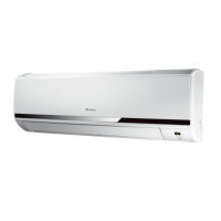
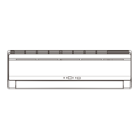
Dimensional drawings of the indoor unit.

3.2 Outdoor Unit

Dimensional drawings of the outdoor unit.

4. Refrigerant System Diagram

5. Schematic Diagram

5.1 Electrical Date

Symbol and color code meanings for wiring.

5.2 Electrical Wiring

Wiring diagrams for indoor and outdoor units.

5.3 Printed Circuit Board

Top and bottom views of the indoor unit PCB.

6. Function and Control

6.1 Remote Controller Description

Explanation of remote controller buttons and their functions.

Unit Indicators and Manual Operation

Unit display symbols, LEDs, and manual ON/OFF button usage.

Operational Modes Overview

Explains cooling, dry, fan, heating, and auto modes.

Specific Control Operations

Details on louvers, sleep, timers, turbo, health, and I Feel functions.

Advanced Control & Protection

Covers fan control, discharge pipe, input current, freeze-up, heating peak-cut, and defrost.

7. Installation Manual

7.1 Tools Required for Installation

List of tools needed for installation.

7.2 Installation Position Selection

Guidelines for choosing indoor and outdoor unit locations.

7.3 Installation of Indoor Unit

Procedures for mounting the indoor unit.

7.4 Installation of Outdoor Unit

Procedures for installing the outdoor unit.

7.5 Test Operation

Steps for verifying installation and initial operation.

9. Troubleshooting

9.1 Precautions before Performing Inspection or Repair

Safety guidelines before inspecting or repairing the unit.

9.2 Confirmation

Verifying power supply and voltage.

9.3 Judgement by Flashing LED of Indoor;Outdoor Unit

Interpreting LED error codes for fault diagnosis.

9.4 How to Check simply the main part

Simple checks for common malfunctions like fan issues.

9.5 2-way, 3-way Valve Appearance

Valve positions for different operations like purging and charging.

10. Removal Procedure

10.1 Removal Procedure of Indoor Unit

Detailed steps for disassembling the indoor unit.

10.2 Removal Procedure of Outdoor Unit

Detailed steps for disassembling the outdoor unit.

11. Care and Cleaning

11. Cleaning Refrigeration System

Procedure for cleaning the refrigeration system.

11.2 Cleaning of Heater Exchanger

Instructions for cleaning the heat exchanger.

Related product manuals