9
7HFKQLFDO,QIRUPDWLRQ
Service Manual
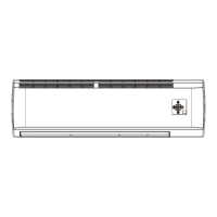
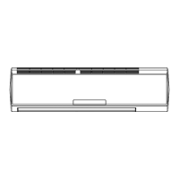
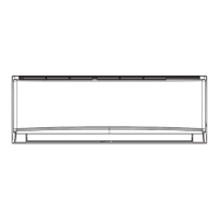
Top View
5.2 PCB Printed Diagram
Indoor unit
Bottom View
1
2
3
456 87 9 11 1210
13
14
15
16
17
1 Fan motor capacitor terminal
2 Live wire
3 Fuse
4 Neutral wire
5
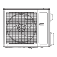
Indoor & outdoor unit
communication cable
terminal
6 6XSHUKLJKIDQOHYHOWHUPLQDO
7 Low fan level terminal
8 Medium fan level terminal
9 +LJKIDQOHYHOWHUPLQDO
10 /HIWULJKWVZLQJWHUPLQDO
11 Auto button
12 /HIWULJKWVZLQJWHUPLQDO
13 Up & down swing terminal
14 Ambient temp sensor
15 Tube temp sensor
16
No.2 double-8 display
terminal
17
No.1 double-8 display
terminal
 Loading...