64
Installation and Maintenance
Service Manual
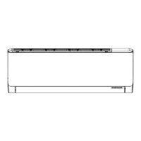
NO. Description
1 Front Panel
2 Display Board
3 Filter Sub-Assy
4 Screw Cover
5 Front Case
6 Guide Louver
7 Axile Bush
8 Helicoid Tongue
9 Air Louver
10 Left Axile Bush
11 Rear Case assy
12 Cross Flow Fan
13 O-Gasket sub-assy of Bearing
14 Ring of Bearing
15 Evaporator Support
16 Evaporator Assy
17 Fan Motor
18 Wall Mounting Frame Sub-assy
19 Connecting pipe clamp
20 Rubber Plug (Water Tray)
21 Stepping Motor
22 Crank
23 Drainage Hose
24 Air Louver 2
25 Electric Box Cover2
26 Electric Box Assy
27 Terminal Board
28 Main Board
29 Power Cord
30 Connecting Cable
31 Connecting Cable
32 Remote Controller
Some models may not contain some parts, please
refer to the actual product.
 Loading...