173
Installation and Maintenance
Service Manual
Step Procedure
b
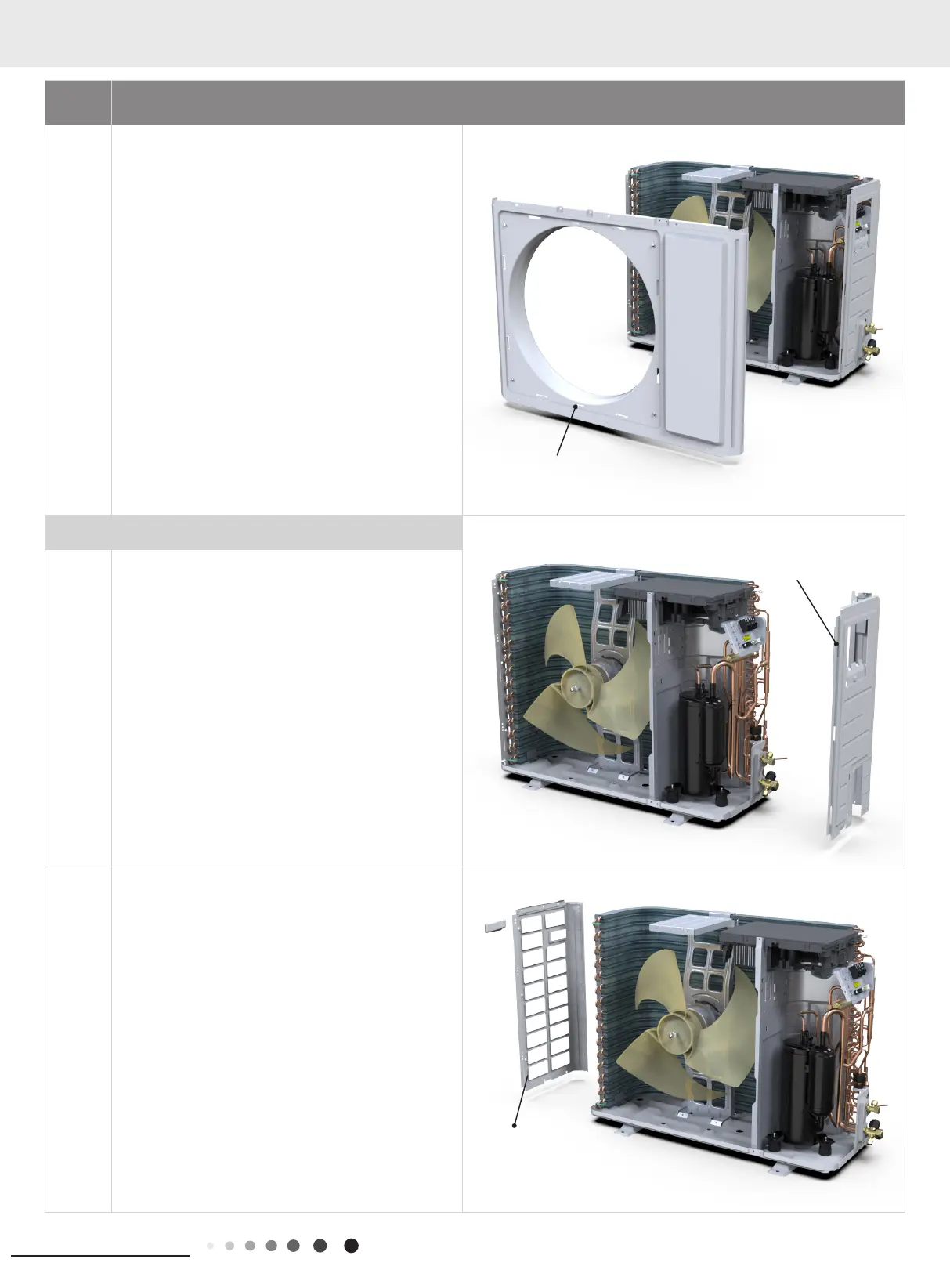
Remove the screws connecting the outer case with
motor support, isolation plate and chassis; lift the outer
case upwards; loosen the clasps of outer case with
right side plate and left side plate, and then remove the
outer case.
3. Remove right&left side plate
a
Remove the screws connecting the right side plate with
electric box assy, valve support, chassis and condenser
side plate, and then remove the right side plate.
b
Remove the screws connecting the left side plate with
chassis, and then remove the left side plate.
panel
left side plate
Right side plate
 Loading...