This document is the Owner's Manual for a TOSOT Inverter Split Air Conditioner. It provides comprehensive information regarding the installation, operation, maintenance, and safety precautions for the appliance.
Function Description:
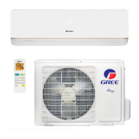
The TOSOT Inverter Split Air Conditioner is designed to provide cooling and heating (for heat pump models) for indoor spaces. It utilizes R32 refrigerant, which is described as a non-polluting refrigerant with no harm to the ozonosphere and a lower influence on the greenhouse effect compared to common refrigerants. The inverter technology contributes to high energy efficiency. The system circulates a special refrigerant to achieve its cooling and heating functions.
Important Technical Specifications:
The manual lists several models: GWH09AAB-K6DNA3A/O, GWH12AAB-K6DNA3A/O, GWH18AAD-K6DNA1A/O, GWH18AAD-K6DNA1B/O, and GWH24AAD-K6DNA1A/O.
The refrigerant used is R32, with a GWP (Global Warming Potential) of 675.
The operating temperature range for cooling-only units is -15°C to 43°C (outdoor temperature), and for heat pump units, it is -20°C to 43°C (outdoor temperature) or -15°C to 43°C (outdoor temperature) for some models.
Indoor side DB/WB (Dry Bulb/Wet Bulb) temperatures for maximum cooling are 32/23°C and for maximum heating are 27/-°C. Outdoor side DB/WB temperatures for maximum cooling are 43/26°C and for maximum heating are 24/18°C.
Minimum room area requirements for installation are provided in a table based on the refrigerant charge amount (kg) and installation type (floor, window mounted, wall mounted, ceiling mounted). For example, for a charge amount of ≤1.2 kg, the minimum room area is 14.5 m² for floor location, 5.2 m² for window mounted, 1.6 m² for wall mounted, and 1.1 m² for ceiling mounted. These values increase with higher charge amounts.
Maximum connection pipe lengths vary by capacity: 15m for 5000-9000 Btu/h units, 20m for 12000 Btu/h units, and 25m for 18000 Btu/h units, and 25-30m for 24000-48000 Btu/h units.
Min length of connection pipe: For units with a standard connection pipe of 5m, there is no limitation. For units with standard connection pipes of 7.5m and 8m, the minimum length is 3m.
Additional refrigerant charging amount (g/m) and refrigerant oil (ml) are specified based on the liquid pipe diameter and prolonged length of the connection pipe. For example, for a Φ6 liquid pipe, the additional refrigerant charging amount is 16 g/m for cooling only/cooling and heating (indoor unit throttle) and 12 g/m for cooling only (outdoor unit throttle).
Usage Features:
The air conditioner is designed for ease of use, with instructions for test operation provided. Users can select AUTO, COOL, DRY, FAN, and HEAT modes via the remote controller. The appliance is suitable for use by children aged 8 years and above and persons with reduced physical, sensory or mental capabilities or lack of experience and knowledge, provided they receive supervision or instruction.
Maintenance Features:
The manual emphasizes that maintenance must be performed by qualified professionals to avoid personal injury or damage. Users are advised not to repair the air conditioner themselves. Regular cleaning and user maintenance should not be performed by children without supervision.
Key maintenance points include:
- Cleaning: Disconnect power supply before cleaning. Do not wash the air conditioner with water or spray water on the indoor unit. After removing the filter, avoid touching fins. Do not use fire or a hair dryer to dry the filter to prevent deformation or fire hazard.
- Filter: Filters should be cleaned regularly.
- Leakage Detection: After installation and removal, leakage detection is a must. This can be done with a leakage detector or soap water. For soap water, apply it to suspected positions and check for air bubbles for more than 3 minutes.
- Refrigerant Handling: If repairs or relocation require refrigerant recovery, the unit must be running in cooling mode. The high-pressure side (liquid valve) should be closed first, followed by the low-pressure side (gas valve) after 30-40 seconds. The unit must be stopped, and power disconnected immediately, with refrigerant recovery not exceeding 1 minute. Liquid and gas valves must be fully closed, and power disconnected before detaching connection pipes during recovery.
- Welding: If cutting or welding refrigerant system pipes, specific steps must be followed: shut down the unit, cut power, eliminate refrigerant, vacuum, clean with N2 gas, cut/weld, and carry back to service spot.
- Refrigerant Filling: Use specialized appliances for R32. Ensure different refrigerants do not contaminate each other. Keep the refrigerant tank upright. Label the system after filling. Avoid overfilling. Perform leakage detection after filling and upon removal.
- Storage and Transportation: Use a flammable gas detector before unloading/opening containers. No fire sources or smoking. Follow local rules and laws.
Safety Precautions:
The manual includes extensive safety warnings and cautions, categorized by "DANGER," "WARNING," "CAUTION," and "NOTICE."
- General Safety:
- Children should be supervised and not play with the appliance.
- Do not connect to multi-purpose sockets.
- Disconnect power supply during cleaning.
- Damaged supply cords must be replaced by the manufacturer or qualified persons.
- Do not extend fingers or objects into air inlet/outlet.
- Do not block air inlet/outlet.
- Do not spill water on the remote controller.
- Turn off and disconnect power immediately if abnormal phenomena occur (overheating cord, abnormal sound, frequent circuit breaker trips, burning smell, indoor unit leaking).
- Use an insulating object for the emergency operation switch.
- Do not step on the outdoor unit or place heavy objects on it.
- Installation Safety:
- Installation must be performed by qualified professionals following electric safety regulations.
- Use a qualified power supply circuit and circuit breaker.
- Install a circuit breaker with suitable capacity (magnet buckle and heating buckle function) to protect against circuit shorts and overload.
- An all-pole disconnection switch with at least 3mm contact separation in all poles must be connected in fixed wiring.
- The air conditioner must be properly grounded by a professional. The yellow-green wire is for grounding only.
- Grounding resistance must comply with national electric safety regulations.
- Ensure power supply matches requirements; install proper cables.
- Properly connect live, neutral, and grounding wires.
- Cut off power before any electrical work.
- Do not power on before finishing installation.
- Keep the interconnection cable away from the copper tube due to high refrigerant circuit temperature.
- Installation must comply with national wiring regulations (NEC and CEC).
- The appliance must be positioned so the plug is accessible.
- All indoor and outdoor unit wires must be connected by a professional.
- Do not extend power connection wire yourself; contact the supplier for a new one if insufficient.
- For units with a plug, the plug must be reachable after installation.
- For units without a plug, a circuit breaker must be installed in the line.
- Relocation must be done by qualified personnel.
- Select a location out of reach of children, animals, or plants; add a fence if unavoidable.
- The indoor unit should be installed close to the wall.
- Do not install where corrosive or flammable gas may leak.
- Do not use extension cords for electrical connections.
- Use specified wire types for electrical connections between units and firmly clamp them.
- Refrigerant-Specific Safety (R32):
- The refrigerant is flammable and can lead to explosion under certain conditions, though flammability is very low.
- Do not use means to accelerate defrosting or clean other than recommended by the manufacturer.
- Repairs by unqualified personnel are dangerous.
- Store the appliance in a room without continuously operating ignition sources (open flames, gas appliances, electric heaters).
- Do not pierce or burn.
- The appliance must be installed, operated, and stored in a room with a floor area larger than specified in table "a" (Safety Operation of Inflammable Refrigerant).
- Strictly follow manufacturer's instructions for repairs.
- Refrigerants do not contain odor.
- Keep the refrigerant circuit free from air or other substances during installation/relocation to prevent pressure rise or compressor rupture.
- Do not charge with non-compliant or unqualified refrigerant.
- Ensure connection pipe is securely connected before the compressor starts running.
- Do not install in rooms with running fire, or drill/burn connection pipes.
- The minimum room area must be met.
- Maintenance areas must be well-ventilated, free of fire sources, and have "no smoking" signs.
- Replace vague or damaged warning marks.
Installation Process:
The manual details the installation process for the outdoor unit:
- Fixing the support: Select a location, fix the support with expansion screws. The support must withstand at least four times the unit weight. The outdoor unit should be at least 3cm above the floor for drain joint installation. The number of expansion screws required varies by cooling capacity.
- Installing the drain joint (cooling and heating units only): Connect the outdoor drain joint to the chassis hole and the drain hose to the drain vent.
- Fixing the outdoor unit: Place the unit on the support and fix its foot holes with bolts.
- Connecting indoor and outdoor pipes: Remove the screw and handle, then the screw cap of the valve. Aim the pipe joint at the bellmouth of the pipe. Pre-tighten the union nut by hand, then tighten with a torque wrench to specified values based on hex nut diameter (e.g., Φ6: 15-20 N·m, Φ19: 70-75 N·m).
- Connecting outdoor electric wire: Remove the wire clip, connect power and signal control wires to the wiring terminal according to color, and fix with screws. Wiring diagrams are provided for different models (09K, 12K, 18K, 24K).
- Neatening the pipes: Place pipes along the wall, bent reasonably (min. semidiameter 10cm). If the outdoor unit is higher than the wall hole, form a U-shaped curve in the pipe to prevent rain entry. Ensure the drain hose is not higher than the indoor unit's outlet pipe hole, is slanted downwards, and is not curved, raised, fluctuant, or placed in water.
Vacuum Pumping:
Detailed steps for vacuum pumping are provided:
- Remove valve caps and refrigerant charging vent nut.
- Connect piezometer charging hose to the gas valve's refrigerant charging vent, and the other hose to the vacuum pump.
- Open the piezometer completely and operate for 10-15 minutes to check if the pressure remains at -0.1MPa.
- Close the vacuum pump and maintain for 1-2 minutes to check for pressure decrease (indicating leakage).
- Remove the piezometer, open liquid and gas valve cores completely with an inner hexagon spanner.
- Tighten screw caps of valves and refrigerant charging vent.
Pipe Expanding Method:
Improper pipe expanding is a common cause of refrigerant leakage. The manual provides a step-by-step guide:
A. Cut the pipe: Confirm length, cut with a pipe cutter.
B. Remove burrs: Use a shaper to remove burrs, preventing them from entering the pipe.
C. Put on insulating pipe: Place suitable insulating pipe.
D. Put on union nut: Remove the union nut from the indoor connection pipe and outdoor valve, then install it on the pipe.
E. Expand the port: Use an expander. A table specifies the "A" dimension (Max/Min) based on outer diameter (e.g., Φ6: 1.3/0.7mm, Φ19: 2.4/2.2mm).
F. Inspection: Check the quality of the expanding port for blemishes. If found, re-expand. Illustrations show smooth and improper expanding surfaces (leaning, damaged, crack, uneven thickness).