EasyManua.ls Logo

Gree GWH24KG-K3DNA6G User Manual

Gree GWH24KG-K3DNA6G
101 pages
To Next Page IconTo Next Page
Page #1 background imageLoading...
Page #1 background image
GREE ELECTRIC APPLIANCES,INC.OF ZHUHAI
Change for Life
Service Manual
Models: GWH18KG-K3DNA5G
GWH18KG-K3DNA6G
GWH18KG-K3DNA9G
GWH18KG-K3DNB1G
GWH18KG-K3DNB2G
GWH18KG-K3DNB4G
GWH24KG-K3DNA5G
GWH24KG-K3DNA6G
GWH24KG-K3DNA9G
GWH24KG-K3DNB1G
GWH24KG-K3DNB2G
GWH24KG-K3DNB4G
(Refrigerant R410A)
Question and Answer IconNeed help?

Do you have a question about the Gree GWH24KG-K3DNA6G and is the answer not in the manual?

Gree GWH24KG-K3DNA6G Specifications

General IconGeneral
Cooling Capacity24000 BTU/h
Energy Efficiency Ratio (EER)3.21
Power Supply220-240V, 50Hz
RefrigerantR410A
Weight (Indoor Unit)12 kg
TypeSplit
Operating Temperature (Cooling)18°C to 43°C
Operating Temperature (Heating)-7°C to 24°C

Summary

Part I : Technical Information

1. Summary

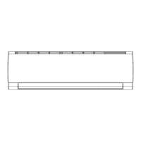
Overview of indoor unit models and their associated images.

Outdoor Unit and Remote Controller

Images and model numbers for outdoor units and remote controller.

2. Specifications

2.1 Specification Sheet

Table listing various parameters and their values for the unit.

3. Outline Dimension Diagram

3.1 Indoor Unit Dimensions

Diagrams showing the dimensions and mounting points of the indoor unit.

2.2 Operation Characteristic Curve

2.3 Capacity Variation Ratio According to Temperature

2.4 Cooling and Heating Data Sheet

2.5 Noise Curve

3.2 Outdoor Unit Dimensions

4. Refrigerant System Diagram

5. Electrical Part

5.1 Wiring Diagram (Indoor Unit)

Electrical schematic showing connections for the indoor unit.

5.1 Wiring Diagram (Outdoor Unit)

5.2 PCB Printed Diagram (Indoor Unit)

5.2 PCB Printed Diagram (Outdoor Unit)

6. Function and Control

6.1 Remote Controller Introduction

Details about the buttons and icons on the remote controller.

Remote Controller Buttons

Remote Controller Operations and Battery Replacement

6.2 Brief Description of Modes and Functions

Indoor Part Functions

Details about indoor unit indicators, display modes, and temperature settings.

Indoor Unit Functions and Malfunctions

Temperature Sensor Malfunctions and Refrigerant Recovery

Outdoor Part

Parameter Compensation and Calibration

Procedures for calibrating and compensating input parameters.

Compressor and Fan Control

Protection Functions

Part II : Installation and Maintenance

Safety Precautions

Important safety instructions to follow during installation and maintenance.

Installation Parts Check and Location Selection

8.4 Electric Connection Requirement

8.5 Installation of Indoor Unit

8.5 Installation of Indoor Unit (Continued)

Continuation of indoor unit installation steps, including piping and drain hose.

8.5 Installation of Indoor Unit (Wiring)

Steps for connecting wires and hanging the indoor unit.

8.6 Installation of Outdoor Unit

8.7 Vacuum Pumping and Leak Detection

8.8 Check after Installation and Test Operation

Maintenance

9.1 Malfunction Display of Indoor Unit

How indoor unit malfunctions are displayed and error codes.

9.2 Procedure of Troubleshooting (Temperature Sensor)

9.2 Procedure of Troubleshooting (Fan Motor)

9.2 Procedure of Troubleshooting (Jumper Cap)

9.2 Procedure of Troubleshooting (Zero-crossing Circuit)

9.2 Procedure of Troubleshooting (Communication Malfunction)

9.2 Procedure of Troubleshooting (Compressor Desynchronizing)

9.2 Procedure of Troubleshooting (Temperature Sensor F3/F4/F5)

9.2 Procedure of Troubleshooting (Overload/Discharge Protection)

9.2 Procedure of Troubleshooting (Capacitor Malfunction)

9.2 Procedure of Troubleshooting (Overload Protection E8)

9.2 Procedure of Troubleshooting (IPM Protection)

9.2 Procedure of Troubleshooting (PFC Protection)

9.2 Procedure of Troubleshooting (Communication E6)

9.2 Procedure of Troubleshooting (Start-up Failure)

9.2 Procedure of Troubleshooting (Overcurrent Protection E5)

9. Other Malfunction

9.3 Troubleshooting for Normal Malfunction

Troubleshooting Common Issues

Addresses problems like unit not starting, poor cooling/heating, and louver issues.

Troubleshooting Air Conditioner Leaks

Troubleshooting Abnormal Sound and Vibration

Exploded View and Parts List

10.1 Indoor Unit

Exploded view and parts list for the indoor unit.

10.1 Indoor Unit Parts List (Continued)

Detailed parts list for various models of the indoor unit.

10.1 Indoor Unit Exploded View (24K)

Exploded view diagram for the 24K indoor unit model.

10.1 Indoor Unit Parts List (24K Models)

Detailed parts list for 24K indoor unit models.

10.2 Outdoor Unit

Exploded view diagram for the outdoor unit.

10.2 Outdoor Unit Parts List

Parts list for outdoor unit models.

10.2 Outdoor Unit Parts List (Continued)

Parts list for outdoor unit models.

10.2 Outdoor Unit Parts List (Continued)

Parts list for outdoor unit models.

Removal Procedure

11.1 Removal Procedure of Indoor Unit

Steps for safely removing parts of the indoor unit.

11.1 Removal Procedure of Indoor Unit (Continued)

Steps for opening panels and removing the front panel of the indoor unit.

11.1 Removal Procedure of Indoor Unit (Continued)

Steps for removing the service cover and front grille assembly of the indoor unit.

11.1 Removal Procedure of Indoor Unit (Continued)

Steps for removing the electrical box and temperature sensor from the indoor unit.

11.1 Removal Procedure of Indoor Unit (Continued)

Steps for removing piping fixtures and the evaporator assembly from the indoor unit.

11.1 Removal Procedure of Indoor Unit (Continued)

Steps for removing motor components and shaft cushion rubber base from the indoor unit.

11.2 Removal Procedure of Outdoor Unit

Steps for safely removing parts of the outdoor unit.

11.2 Removal Procedure of Outdoor Unit (Continued)

Steps for removing panels and side plates from the outdoor unit.

11.2 Removal Procedure of Outdoor Unit (Continued)

Steps for removing the fan motor and electrical box from the outdoor unit.

11.2 Removal Procedure of Outdoor Unit (Continued)

Steps for removing soundproof sponge and the 4-way valve assembly from the outdoor unit.

11.2 Removal Procedure of Outdoor Unit (Continued)

Steps for removing the compressor and condenser sub-assembly from the outdoor unit.

Appendix

Appendix 1: Reference Sheet of Celsius and Fahrenheit

Conversion table for temperature units.

Appendix 2: Configuration of Connection Pipe

Guidelines for connection pipe lengths, refrigerant oil, and charging amounts.

Appendix 3: Pipe Expanding Method

Detailed instructions for expanding refrigerant pipes to prevent leaks.

Appendix 4: Temperature Sensor Resistance Tables

Resistance values for indoor, outdoor, and discharge temperature sensors.

Appendix 4: Temperature Sensor Resistance Tables (Outdoor Discharge)

Resistance values for outdoor discharge temperature sensors at various temperatures.

Related product manuals