EasyManua.ls Logo

Gree KFR-25GW/A12 - User Manual

Gree KFR-25GW/A12
131 pages
To Next Page IconTo Next Page
Loading...
1
Summary and features
Models
Remarks
Summary and features
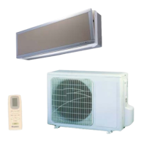
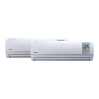
Bird Triad-Split Type
Bird Single-Split Type

Table of Contents

Question and Answer IconNeed help?

Do you have a question about the Gree KFR-25GW/A12 and is the answer not in the manual?

Gree KFR-25GW/A12 Specifications

General IconGeneral
BrandGree
ModelKFR-25GW/A12
CategoryAir Conditioner
LanguageEnglish

Summary

1 Summary and features

2 Technical and specifications

3 Spare part name

4 Outline and installation dimension

5 System diagram

5.1 System diagram for cooling only type

Illustrates the refrigerant flow for cooling-only operation.

5.2 System diagram for cooling;heating type

Shows refrigerant flow for both cooling and heating modes.

6 Circuit diagram

7 PCB function manual and operation method

7.1 PCB function manual 1

Details temperature parameters, fundamental functions, and cooling mode operations.

7.1.1 The conditions and processes of dehumidifying

Explains DRY mode conditions, processes, and temperature settings.

7.1.2 Protection Functions

Covers overcurrent and antifreezing protection mechanisms.

7.1.2.3 HEAT Mode

Details the conditions and processes for heating operation.

7.1.2.3.2 The conditions and processes of defrosting

7.1.2.3.3 Protection function

Overcurrent protection

Details overcurrent protection, high temp avoidance, and noise cancellation.

Noise cancellation protection

Explains noise cancellation during unit shutdown.

7.1.3 Other control

Swing motor

Covers swing motor, buzzer, and run indicator functions.

7.1.3.4 Manual switch function (under indoor unit front panel)

Explains functions of manual switches like AUTO, TEST, RUN, and STOP.

7.1.3.5 Sleep function

Details sleep mode temperature and fan speed adjustments.

7.1.3.6 Auto FAN

Describes automatic fan speed selection.

7.1.3.7 Timing Function

7.2 PCB function manual 2

7. 2. 1 Temperature parameter

Defines room set, ambient, evaporator, and condenser temperatures.

7. 2. 2 Foundamental functions

Covers startup time span, COOL mode conditions, and startup behavior.

7.2.2.2 Protection Functions

Details overcurrent and antifreezing protection in COOL mode.

7.2.2.2 DRY Mode

7.2.2.3 HEAT Mode

7.2.2.3.2 The conditions and processes of defrosting

7.2.2.3.3 Protection function

Overcurrent protection

Covers overcurrent protection.

Avoiding high temp.

Addresses avoiding high temperature issues.

7.2.3 AUTO mode

7.2.3 Other control

Buzzer

Controls buzzer feedback.

Run indicator

Manages the run indicator light.

Swing motor

Controls the swing motor operation.

7.2.3.4 Sleep function

7.2.3.5 Autokey (Under the indoor unit front panel)

7.2.3.6 Auto FAN

7.3 Names and functions of wireless remote control of each part

7.4 Names and functions of wireless remote control(Remove the cover)

7.5 COOL mode operation

7.6 HEAT mode operation

7.7 DRY mode operation

7.8 AUTO mode operation

7.9 TIMER operation mode

7.10 SLEEP mode operation

7.11 How to insert batteries

Guide for operation procedure

Outlines general and selected procedures for remote operation.

Inserting batteries

Provides instructions for inserting batteries into the remote control.

8 Dissassembly Procedures

8.1 Disassembly procedures for indoor unit

Details steps for disassembling the indoor unit components.

Disassemble the front case

Steps to remove the front case of the indoor unit.

Disassemble water-tray

Steps to remove the water tray.

Disassemble evaporator assy

Steps to remove the evaporator assembly.

Disassemble the motor and cross flow fan

8.2 Disassembly procedures for the smaller outdoor unit

Disassemble the top cover and handle

Steps to remove the top cover and handle.

Disassemble the rear grill

Steps to remove the rear grill.

Disasssemble the front grill

Steps to remove the front grill.

Disassemble the electric box

Disassemble the right side plate

Disassemble the axial flow fan

Disassemble the motor and motor support

Disassemble the 4-way valve

Disassemble the capillary

Disassemble the valve

Disassemble the compressor

8.3 Disassembly procedures for the big outdoor unit

Disassemble the top cover and handle

Steps to remove the top cover and handle.

Disassemble the rear grill

Steps to remove the rear grill.

Disassemble front grill

Steps to remove the front grill.

Disassemble the electric box

Disassemble the right side plate

Disassemble the Axial flow fan

Disassemble the motor and motor support

Disassemble the 4-way valve

Disassemble the capillary

Disassemble the valve

Disassemble the compressor

8.4 Disassembly procedures for the plastic case outdoor unit

Disassemble the right handle

Steps to remove the right handle.

Disassemble the front grill

Steps to remove the front grill.

Disassemble the front grill

Disassemble the rear grill

Disassemble the electric box cover

Disassemble the supporting plate

Disassemble the electric box

Disassemble the axial flow fan

Disassemble the motor and motor support

Disassemble the 4-way valve

Disassemble the capillary

Disassemble the valve

Disassemble the compressor

9 Explosive view and spare parts list

9.1 Explosive view of indoor unit

Visual exploded view of indoor unit components.

9.2 Spare parts list of indoor unit

9.5 Disassembly of Components of Big Outdoor Unit

9.6 Detail List of Components of big Outdoor Unit

9.7 Disassembly of Components of Plastic Case Outdoor Unit

9.8 Detail List of Components of Plastic Case Outdoor Unit

10 Maintenance and Repair

10.1 Clean Panel

Instructions for removing, cleaning, and installing the indoor unit panel.

10.2 Clean Air Filter

Instructions for removing, cleaning, and installing the air filter.

11 Installation Guide

11.1 Select of Install Location

Guidance on choosing suitable locations for indoor and outdoor units.

11.2 Install Indoor Unit

Install of rear panel

Steps for mounting the rear panel of the indoor unit.

Make piping hole

Instructions for creating piping holes.

Install drainage hose

Guidance on correctly installing the drainage hose.

Install connecting pipe

Steps for connecting the refrigerant pipes.

5 Electric wiring:

6 Install indoor unit

11.3 Install Outdoor Unit

1 Install connect pipe

Steps for connecting and tightening the refrigerant pipes.

2 Wiring connection

Steps for connecting the electrical wiring to the outdoor unit.

3 Vaccumize and Leakage Detect

4 Drainage of condensate of outdoor unit

11.4 Check Items for Trial Run and after Installation

1 Trial Run

Steps for preparing and conducting the initial trial run.

2 Check Items after Installation

List of checks to perform after installation is complete.

12 Malfunction Analysis

Unit cannot start

Troubleshooting guide for when the unit fails to start.

Bad cooling (heating)

Troubleshooting guide for cooling or heating performance issues.

Outdoor unit and compressor dont run when unit is cooling or heating

When unit is cooling or heating, compressor runs but outdoor fan doesnt run

When cooling or heating, outdoor fan runs, compressor doesnt run.

Water leakage

Abnormal sound and shake

Related product manuals