Ultra thin split unit series
5
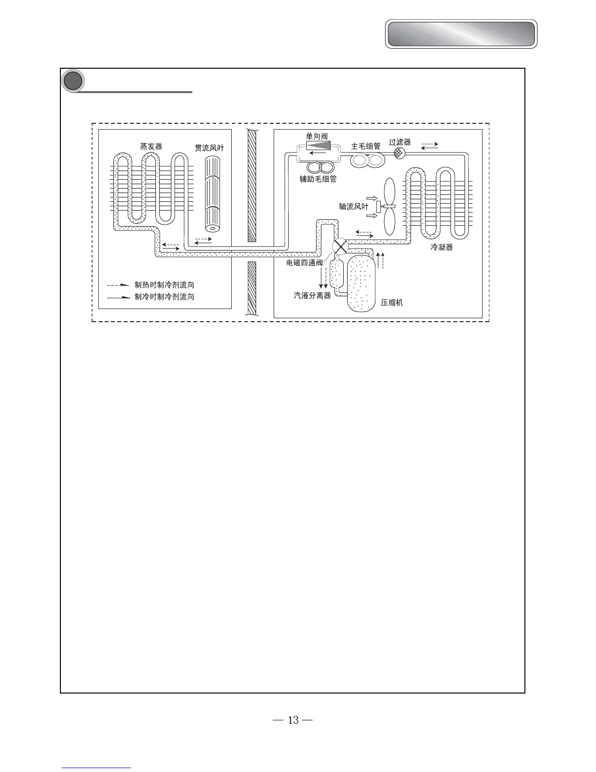
System principle diagram
When the power is on, indoor unit , outdoor unit start to work. When the system is runnng in cool mode, the compressor
sucks low-temperature, low-pressure, refrierant gas from indoor evaporator and then discharges high-temperature, high-pressure
refrigerant gas into outdoor heat exchanger. With the help of axial flow fan, the gas transfers its latent heat into outdoor air and
becomes high-pressure refrigerant liquid. The liquid is throttled by the capillary and changes into low-temperature and low-pressure
liquid and then flows into indoor heat exchanger. With the help of centrifugal fan, the liquid evaporates into low-temperature
refrigerant gas and indoor air is cooled down. The refrigerant gas is sucked into the compressor and the cycle introduced above
goes on and on, and the demanded low temperature environment is maintained.
When the system operates in heat mode, 4-way valve changes its way and the refrigerant flows in the reversible cycle as
the cool mode. The refrigerant discharges its latent heat in the indoor heat exchange exchanger, and sucks heat from outdoor heat
exchanger and forms the heat pump cycle. This cycle goes on and on, and the demanded high temperature environment is maintenained.
 Loading...