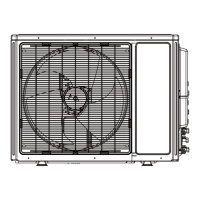
SYSTEM REQUIREMENTS
REFRIGERANT CHARGE
ELECTRICAL REQUIREMENTS
Notes: 1) System must be on a single dedicated circuit.
2) Main power is supplied to the outdoor unit.
3) Use table above to size over current protection.
4) Follow all local building codes and NEC (National Electrical Code) regulations.
Interconnecting Cable: Recommended cable - 14/4 AWG stranded bare copper conductors THHN 600V unshielded wire
Note: Use shield cable if installation is in close proximity of RF and EMI transmitting devices.
Unit Size (BtuH)
L
iquid Line
i
n(mm)
S
uction/Gas Line
i
n(mm)
18,000
Port A 1/4 (6) 3/8 (9.5)
Port B 1/4 (6) 3/8 (9.5)
P
ort A 1/4 (6) 3/8 (9.5)
24,000 Port B 1/4 (6) 3/8 (9.5)
P
ort C 1/4 (6) 3/8 (9.5)
P
ort A 1/4 (6) 3/8 (9.5)
3
0,000
Port B 1/4 (6) 3/8 (9.5)
P
ort C 1/4 (6) 3/8 (9.5)
Port D 1/4 (6) 3/8 (9.5)
Port A 1/4 (6) 3/8 (9.5)
36,000
Port B 1/4 (6) 3/8 (9.5)
Port C 1/4 (6) 3/8 (9.5)
Port D 1/4 (6) 3/8 (9.5)
Port E 1/4 (6) 3/8 (9.5)
Port A 1/4 (6) 3/8 (9.5)
Port B 1/4 (6) 3/8 (9.5)
42,000 Port C 1/4 (6) 3/8 (9.5)
Port D 1/4 (6) 3/8 (9.5)
Port E 1/4 (6) 3/8 (9.5)
Unit Size Max Total Pipe
Min
Equivalent Max Equivalent Max Elev btwn Max Elev btwn
(BtuH) Length ft(m) Pipe Length ft(m) Pipe Length ft(m) IND Units ft(m) IND&OTDUnits ft(m)
18,000 65 (20) 10 (3) 33 (10) 33 (10) 33 (10)
24,000 197 (60) 10 (3) 65 (20) 33 (10) 33 (10)
30,000 230 (70) 10 (3) 82 (25) 33 (10) 49 (15)
36,000 246 (75) 10 (3) 82 (25) 33 (10) 49 (15)
42,000 246 (75) 10 (3) 82 (25) 33 (10) 49 (15)
Unit Size
Voltage
Min Circuit Max Overcurrent Main Power
(BtuH) Amps (MCA) Protection (MOP) Wire Size (AWG)**
18,000 208/230v - 1ph 60hz 16 25 12
24,000 208/230v - 1ph 60hz 23 30 10
30,000 208/230v - 1ph 60hz 20 30 10
36,000 208/230v - 1ph 60hz 23 35 8
42,000 208/230v - 1ph 60hz 24 40 8
**Main power wire from electrical panel to outdoor unit. AWG based on 240VAC Single Phase, 100 ft. distance 1-way, max. 5% allowable voltage drop.
REFRIGERANT PIPE LENGTHS
Unit Size Refrigerant Factory System Max Pipe Length w/out Additional
(BtuH) Type Charge oz(kg) adding Refrig ft(m) Charge oz/ft (g/m)
18,000 R-410A 56.5 (1.6) 33 (10) 0.2 (20)
24,000 R-410A 77.6 (2.2) 98 (30) 0.2 (20)
30,000 R-410A 98.7 (2.8) 131 (40) 0.2 (20)
36,000 R-410A 128.8 (3.65) 131 (40) 0.2 (20)
42,000 R-410A 128.8 (3.65) 131 (40) 0.2 (20)
4 37
DIAGNOSTIC CODES
X-fan Mode
Indoor Evap Coil Temperature
Sensor Malfunction
Gas valve temperature sensor
is open/short circuited
System Configuration
Malfunction
Communication wire error or
electronic expansion valve
malfunction
Wrong connection of communication
wire or malfunction of electronic
expansion valve
System High Pressure
Indoor Anti-Freeze Protection
Low Pressure Protection
Compressor High Discharge
Temperature Protection
Overcurrent Protection
Communication Malfunction
Mode conflict (Indoor units
calling for simutaneuously
Heating and Cooling)
Operation status
1) Loose or bad connection between sensor and control board
2) Indoor Evap Coil temperature sensor damaged
3) Control board malfunction
Hardware malfunction
1) No jumper cap inserted on the control board
2) Incorrect or damaged jumper cap on control board
3) Indoor and outdoor units are not compatible
Operation status
Hardware malfunction
1) Over charged with refrigerant
2) Blocked or dirty outdoor coil
3) Extreme outdoor ambient conditions
1) Low return airflow
2) Indoor fan speed is too low
3) Indoor coil is blocked or dirty
1) Low on refrigerant
2) Pressure sensor is damaged
Please refer to the malfunction analysis (discharge
temperature, overload) in service manual
1) Supply voltage is unstable
2) Supply voltage is too low and system load is too high
3) Indoor coil is blocked or dirty
1) Communication cable is mis-wired between indoor
and outdoor units
2) Indoor or Outdoor control board malfunction
Operation status
AL
b5
b7
C5
dd
dn
E1
E2
E3
E4
E5
E6
E7
Y
ellow
3 flashes
and 1 sec Off
7 flashes
and 1 sec Off
5 flashes
and 1 sec Off
Continuous
On
R
ed
9 flashes
and 1 sec Off
Troubleshooting
The unit has onboard diagnostics. The outdoor unit will provide status indicators. The indoor
wall unit and remote controller will display error codes. The following is a summary of the
codes with explanation:
I
ndoor Unit
& Remote
Display
O
utdoor Unit Indicators
Malfunction Name Possible Causes
 Loading...