HVLS Touchscreen Control4
Touchscreen with Recessed Mount Kit
The following instructions apply to touchscreen control
installations provided with the recessed mount kit.
1. Mark and cut a 5.8 x 3.25 inch opening in the
surface of the wall for installation of the recessed
mounting junction box.
Wall Opening
5.8 in. x 3.25 in.
2. Remove the appropriate pre-scored knockout from
the recessed mounting junction box for the RJ-12
communication cable from the control panel.
3. Route the RJ-12 cable through the knockout
opening and secure appropriately.
4. Set the recessed mounting junction box in the wall
opening and secure to the wall using the attached
mounting screws. Tighten the mounting screws
until hand-tight, alternating to ensure pressure is
distributed evenly.
5. Plug the RJ-12 cable into the open port on the rear
side of the touchscreen interface.
6. Mount the touchscreen interface to the recessed
mounting junction box using the included
hardware.
7. Snap the decorative trim cover into the front of the
touchscreen interface.
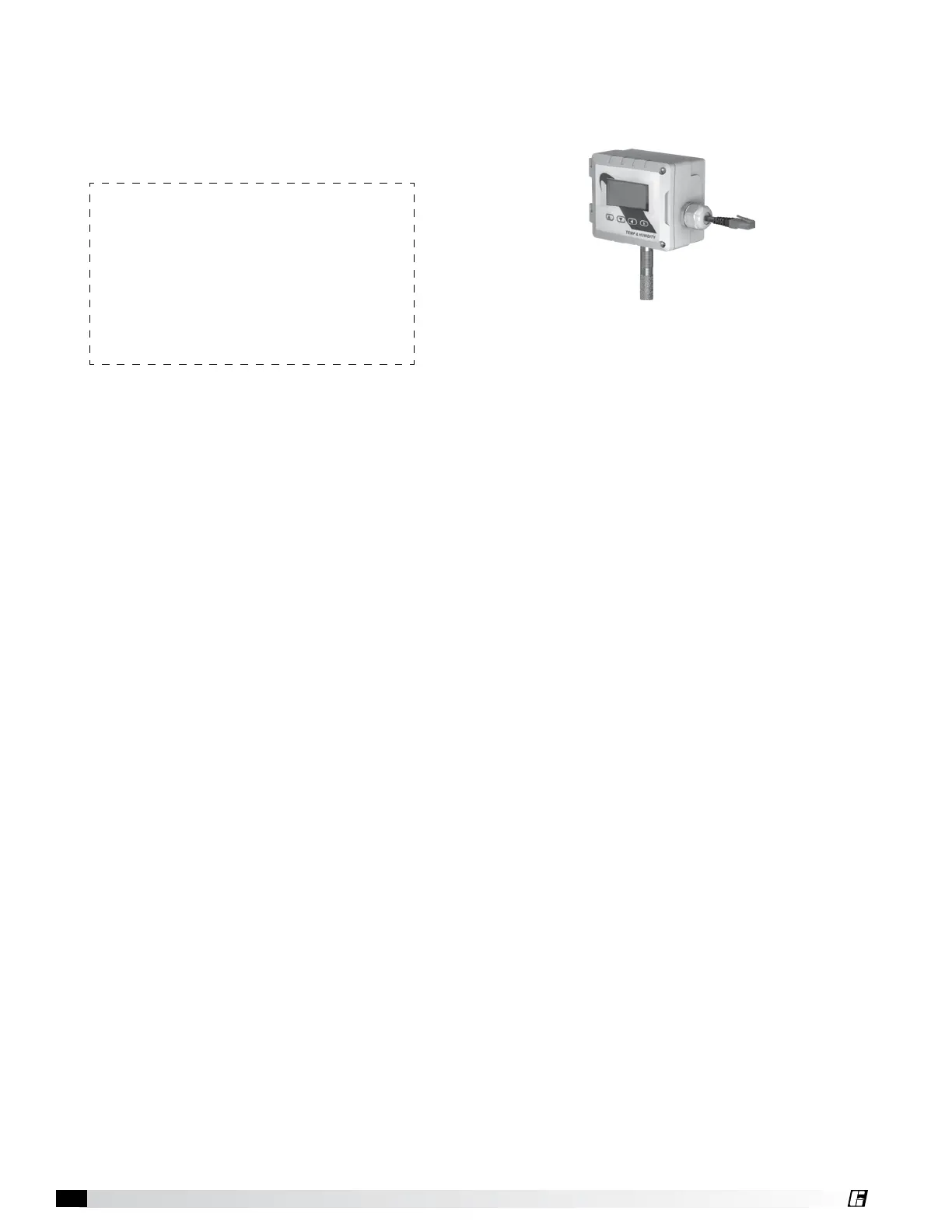
Temperature/Humidity Sensor (Optional)
The following instructions apply to touchscreen control
installations that were provided with the optional
temperature/humidity sensor package.
1. Plug one end of a shielded, twisted pair CAT-5e
cable that was provided with the temperature/
humidity sensor package into the 2-way RJ45
splitter located at the top of the downtube on
the last fan in the daisy chain. For daisy-chain
communication wiring between fans, refer to
instructions on page 5.
IMPORTANT: Touchscreen controls, temperature/
humidity sensors, and HVLS fans must be installed with
the supplied CAT-5e communication cable or shielded,
twisted pair CAT-5e (by others) that complies with the
following specifications. Cable must be twisted pair,
shielded 26 ga. CAT-5e cable with a drain wire and must
be compliant with ISO 11801. Cable must use shielded
RJ45 connectors with a soldered drain and wiring
configuration must follow EIA/TIA T568B wiring pinout.
Individual CAT-5e cable lengths must not exceed 200 ft.
in order to prevent network communication issues.
2. Plug the other end of the shielded, twisted pair
CAT-5e cable into the shielded 2-way RJ45 splitter
located on the temperature/humidity sensor
labelled “CEILING”.
3. Open the front of the enclosure on the temperature/
humidity sensor labelled “CEILING” by turning the
slotted screws in the enclosure one quarter turn.
4. Mount the temperature/humidity sensor labelled
“CEILING” in the desired mounting location using
the three mounting holes on the inside of the
enclosure (mounting hardware provided by others
to accommodate various mounting surfaces).
5. Close the front of the enclosure on the
temperature/humidity sensor labelled “CEILING”.
6. Plug one end of a second shielded, twisted
pair CAT-5e cable that was provided with the
temperature/humidity sensor package into the
shielded 2-way RJ45 splitter on the temperature/
humidity sensor labelled “CEILING”.
7. Plug the other end of the shielded, twisted pair
CAT-5e cable into the shielded 2-way RJ45 splitter
located on the temperature/humidity sensor
labelled “ROOM”.
8. Repeat steps 3-5 to mount the temperature/
humidity sensor labelled “ROOM” at occupant
height.

 Loading...