Do you have a question about the Greenlee DM-20 and is the answer not in the manual?
Explains the purpose and meaning of safety symbols used in the manual.
Defines DANGER, WARNING, and CAUTION hazard levels and their consequences.
Precautions against moisture, damage, lead condition, and intended use to prevent shock and fire.
Warns against exceeding rated voltage and touching test lead tips to prevent electric shock.
Safety rules regarding operating with the case open or before opening it.
Importance of using correct fuse type for overvoltage protection to prevent shock.
Safety during voltage/current measurement and potential impact of electromagnetic interference.
Caution against changing measurement function while test leads are connected to avoid injury or damage.
Cautions against attempting repair and exposing the unit to extreme temperatures or humidity.
Importance of correct selector and test lead connections to prevent blown fuses.
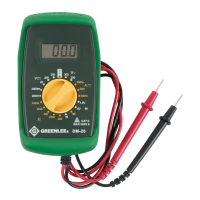
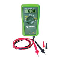
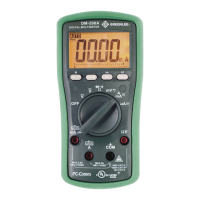
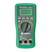
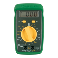
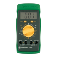
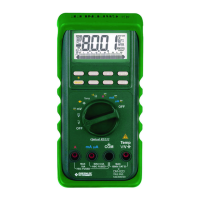
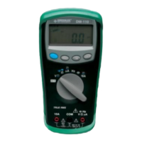
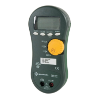
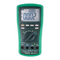
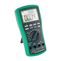
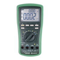
Identifies key parts of the multimeter like display, selector, and test leads.
Explains the meaning of various icons shown on the multimeter's LCD display.
Explains the meaning of symbols marked on the multimeter unit itself.
Warns that contact with live circuits during operation can cause severe injury or death.
Table detailing measurement values and corresponding selector settings for proper operation.
Illustrates how to perform a voltage measurement with the multimeter.
Illustrates how to perform a current measurement with the multimeter.
Illustrates how to perform a resistance measurement with the multimeter.
Illustrates how to perform a continuity check with the multimeter.
Illustrates how to perform a diode measurement with the multimeter.
Specifies the accuracy and burden voltage for DC current measurements.
Specifies the accuracy, frequency range, and input impedance for AC voltage.
Specifies the accuracy and input impedance for DC voltage measurements.
Specifies the accuracy and typical open circuit voltage for resistance measurements.
Specifies test current/threshold and accuracy for battery, diode, and continuity tests.
Details the multimeter's display type, count, and automatic polarity feature.
Specifies the measurement sampling rate and accuracy change with temperature.
Details overload protection, fuses, and measurement category (Category II, 300V).
Lists acceptable operating and storage temperature, humidity, and altitude.
Specifies the type of battery required for the unit.
Defines Category I as signal level for electronic and telecommunication equipment.
Defines Category II as local level for appliances and portable equipment.
Defines Category III as distribution level for installed machines and building systems.
Defines Category IV as primary supply level for overhead lines and utility equipment.
Cautions against attempting repair and exposing the unit to extreme environments during maintenance.
Step-by-step guide for safely replacing the battery and fuse.
Instructions for cleaning the multimeter case with mild detergent.
States the limited lifetime warranty for defects in workmanship and material, excluding normal wear and abuse.
Instructions for contacting customer service for test instrument repairs and obtaining return authorization.
Information on obtaining repair cost quotes for items not covered under warranty.
Advice to check batteries before returning a test instrument for service.
| Continuity Test | Yes |
|---|---|
| Diode Test | Yes |
| Power Supply | 9V battery |
| Safety Rating | CAT III 600V |
| Display | LCD |
| AC Voltage Range | 200V, 600V |
| DC Current Range | 200µA to 10A |
| Display Count | 2000 |
| Resistance Range | 200Ω, 2kΩ, 20kΩ, 200kΩ, 2MΩ |