Page 11
11. BALANCING THE UNIT (RNC 1.0 & RNC12 ONLY)
TOOLS REQUIRED TO
BALANCE THE HRV/ERV
•
A Magnehelic gauge capable of
measuring 0 to 2.0 inch of water
(0 to 500 Pa) and two (2)
plastic hoses.
• A balancing reference chart located
on the HRV/ERV access door panel.
CONSIDERATION WHEN
BALANCING THE HRV/ERV
• Seal all the unit ductwork with tape.
Close all windows and doors.
•
Insure all exhaust devices such as range
hood, dryer and bathroom fans are off.
• That the integrated balancing
dampers located in the collars are
fully open.(Fresh Air damper ref Fig.
11.5, Stale Air damper ref Fig. 11.6)
• Make sure that all filters are clean
and that there is no obstruction in
ductwork
• Make sure that the forced air system
blower is “ON” when connected to an
existing forced air system ductwork.
•
If it is a direct duct system installation
ensure forced air system blower
is “OFF”.
IMPORTANT: Insure the HRV/ERV has
completed the defrost sequence. That
the dehumidistat is deactivated by
turning the round dial to the “OFF”
position, the Range is” NORMAL”, the
mode is “CONT” and the Cycle per Hour
is set at “0/0”.
NOTE: The unit is considered balanced
even if there is a difference of ±10 cfm
(or ± 5 l/s or 17 m³/h) between the two
air flows
Note to installer: For installation
purposes, the RNC 1.0 & RNC12 are
designed with pre-determined airflow
speed values that are stored in memory.
The RNC 1.0 & RNC12 platform are
designed and can be equipped with the
Duotrol™ speed & balancing control
system kit. (Item: 102801) This factory
option must be present to control the
motors independently, when more
accurate airflow settings are required
or for testing purposes. Please contact
Greentek at 1-888-724-5211
for further instructions/information
on this process.
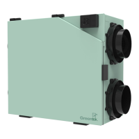
BALANCING PROCEDURES WITH INTEGRATED DAMPERS
Step 1: Place the Magnehelic gauge on a level surface and
adjust the needle to zero.
Step 2: Connect the two (2) plastic hoses to the gauge on
the HIGH & LOW pressure connections.
Step 3: Once the total ventilation requirements are
determined, you can start balancing the HRV/ERV.
(Refer to 1. Ventilation Requirements)
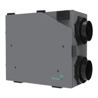
Step 4: Remove the four (4) nylon knock out seals located
on the HRV/ERV access door. (Ref Fig 11.3)
Fig 11.3
Remove all four (4)
nylon knock out seals.
Do not discard.
screw
Front
Stale
Air
HIGHHIGH HIGHHIGH
LOW
LOW LOWLOW
screw
Front
Fresh
Air
Air ViciéAir frais
Enlever les quatre
(4) bouchons
à défoncer de nylon.
Ne pas les jeter.
HAUTHAUT
BAS
BAS
HAUT
HAUT
BAS
BAS
Vis d'adjustement
Devant
Air
vicié
Vis d'adjustement
Devant
Air
frais
Pressure / Pression Fresh air / Air frais Stale air / Air vicié
IN. W.G. Pascal CFM
L/s
CFM
L/s
PO. d’eau (Pa) PCM PCM
0.50 125 - - 161 76
0.53 132 - - 159 75
0.56 139 - - 156 74
0.59 147 - - 153 72
0.62 154 - - 149 70
0.65 162 - - 146 69
0.68 169 - - 142 67
0.71 177 - - 138 65
0.74 184 149 70 133 63
0.77 192 147 69 129 61
0.80 199 144 68 124 59
0.83 207 141 67 119 56
0.86 214 138 65 114 54
0.89 222 133 63 109 51
0.92 229 128 60 103 49
0.95 237 123 58 97 46
0.98 244 116 55 91 43
1.01 252 109 51 85 40
1.04 259 101 48 78 37
1.07 267 93 44 71 34
1.10 274 84 40 64 30
1.13 281 74 35 57 27
1.16 289 64 30 50 24
1.19 296 53 25 42 20
1.22 304 41 19 34 16
1.25 311 29 14 26 12
Step 5: Connect the two (2) plastic hoses from the gauge
to the HIGH & LOW balancing pressure taps on the fresh
or stale air side located on the HRV/ERV access door
(Ref Fig 11.4)
Fig 11.4
Fresh
Air
Stale
Air
Remove all four (4)
nylon knock out seals.
Do not discard.
screw
Front
Stale
Air
HIGHHIGH HIGHHIGH
LOW
LOW LOWLOW
screw
Front
Fresh
Air
Air ViciéAir frais
Enlever les quatre
(4) bouchons
à défoncer de nylon.
Ne pas les jeter.
HAUTHAUT
BAS
BAS
HAUT
HAUT
BAS
BAS
Vis d'adjustement
Devant
Air
vicié
Vis d'adjustement
Devant
Air
frais
Pressure / Pression Fresh air / Air frais Stale air / Air vicié
IN. W.G. Pascal CFM
L/s
CFM
L/s
PO. d’eau (Pa) PCM PCM
0.50 125 - - 161 76
0.53 132 - - 159 75
0.56 139 - - 156 74
0.59 147 - - 153 72
0.62 154 - - 149 70
0.65 162 - - 146 69
0.68 169 - - 142 67
0.71 177 - - 138 65
0.74 184 149 70 133 63
0.77 192 147 69 129 61
0.80 199 144 68 124 59
0.83 207 141 67 119 56
0.86 214 138 65 114 54
0.89 222 133 63 109 51
0.92 229 128 60 103 49
0.95 237 123 58 97 46
0.98 244 116 55 91 43
1.01 252 109 51 85 40
1.04 259 101 48 78 37
1.07 267 93 44 71 34
1.10 274 84 40 64 30
1.13 281 74 35 57 27
1.16 289 64 30 50 24
1.19 296 53 25 42 20
1.22 304 41 19 34 16
1.25 311 29 14 26 12
Step 6: Set the unit on high speed by connecting the Vectra
EHC-1.0 controller to the HRV/ERV, power “ON” and select
the 20MIN/HR operating mode by pressing the “PREF”
button on the Vectra EHC 1.0 control.
ATTENTION: If there is no control present on the RNC 1.0,
will automatically run on a continuous high speed operating
mode.
Step 7:
To adjust the (fresh air), ensure the plastic hoses
from the gauge are connected to the HIGH & LOW balancing
pressure taps on the fresh air side located on the HRV/ERV
access door. (Ref Fig 11.4). Adjust the fresh airflow integrated
balancing damper adjustment screw clockwise until you
reach the calculated fresh airflow requirements. (Ref Fig
11.5 ).
Fig 11.5
Fresh
Air
Stale
Air
Remove all four (4)
nylon knock out seals.
Do not discard.
screw
Front
Stale
Air
HIGHHIGH HIGHHIGH
LOW
LOW LOWLOW
screw
Fresh
Air
Air ViciéAir frais
Enlever les quatre
(4) bouchons
à défoncer de nylon.
Ne pas les jeter.
HAUTHAUT
BAS
BAS
HAUT
HAUT
BAS
BAS
Vis d'adjustement
Devant
Air
vicié
Vis d'adjustement
Devant
Air
frais
Pressure / Pression Fresh air / Air frais Stale air / Air vicié
IN. W.G. Pascal CFM
L/s
CFM
L/s
PO. d’eau (Pa) PCM PCM
0.50 125 - - 161 76
0.53 132 - - 159 75
0.56 139 - - 156 74
0.59 147 - - 153 72
0.62 154 - - 149 70
0.65 162 - - 146 69
0.68 169 - - 142 67
0.71 177 - - 138 65
0.74 184 149 70 133 63
0.77 192 147 69 129 61
0.80 199 144 68 124 59
0.83 207 141 67 119 56
0.86 214 138 65 114 54
0.89 222 133 63 109 51
0.92 229 128 60 103 49
0.95 237 123 58 97 46
0.98 244 116 55 91 43
1.01 252 109 51 85 40
1.04 259 101 48 78 37
1.07 267 93 44 71 34
1.10 274 84 40 64 30
1.13 281 74 35 57 27
1.16 289 64 30 50 24
1.19 296 53 25 42 20
1.22 304 41 19 34 16
1.25 311 29 14 26 12
Fresh
Air
Stale
Air
Remove all four (4)
nylon knock out seals.
Do not discard.
screw
Front
Stale
Air
HIGHHIGH HIGHHIGH
LOW
LOW LOWLOW
screw
Front
Fresh
Air
Air ViciéAir frais
Enlever les quatre
(4) bouchons
à défoncer de nylon.
Ne pas les jeter.
HAUTHAUT
BAS
BAS
HAUT
HAUT
BAS
BAS
Vis d'adjustement
Devant
Air
vicié
Vis d'adjustement
Devant
Air
frais
Pressure / Pression Fresh air / Air frais Stale air / Air vicié
IN. W.G. Pascal CFM
L/s
CFM
L/s
PO. d’eau (Pa) PCM PCM
0.50 125 - - 161 76
0.53 132 - - 159 75
0.56 139 - - 156 74
0.59 147 - - 153 72
0.62 154 - - 149 70
0.65 162 - - 146 69
0.68 169 - - 142 67
0.71 177 - - 138 65
0.74 184 149 70 133 63
0.77 192 147 69 129 61
0.80 199 144 68 124 59
0.83 207 141 67 119 56
0.86 214 138 65 114 54
0.89 222 133 63 109 51
0.92 229 128 60 103 49
0.95 237 123 58 97 46
0.98 244 116 55 91 43
1.01 252 109 51 85 40
1.04 259 101 48 78 37
1.07 267 93 44 71 34
1.10 274 84 40 64 30
1.13 281 74 35 57 27
1.16 289 64 30 50 24
1.19 296 53 25 42 20
1.22 304 41 19 34 16
1.25 311 29 14 26 12
Step 8: To adjust the (stale air), ensure the plastic hoses
from the gauge are connected to the HIGH & LOW balancing
pressure taps on the stale air side located on the HRV/ERV
access door. (Ref Fig 11.4). Adjust the stale airflow integrated
balancing adjustment screw until you reach the calculated
stale airflow requirements. (Ref Fig 11.6).
Fig 11.6
Fresh
Air
Stale
Air
Remove all four (4)
nylon knock out seals.
Do not discard.
screw
Front
Stale
Air
HIGHHIGH HIGHHIGH
LOW
LOW LOWLOW
screw
Front
Fresh
Air
Air ViciéAir frais
Enlever les quatre
(4) bouchons
à défoncer de nylon.
Ne pas les jeter.
HAUTHAUT
BAS
BAS
HAUT
HAUT
BAS
BAS
Vis d'adjustement
Devant
Air
vicié
Vis d'adjustement
Devant
Air
frais
Pressure / Pression Fresh air / Air frais Stale air / Air vicié
IN. W.G. Pascal CFM
L/s
CFM
L/s
PO. d’eau (Pa) PCM PCM
0.50 125 - - 161 76
0.53 132 - - 159 75
0.56 139 - - 156 74
0.59 147 - - 153 72
0.62 154 - - 149 70
0.65 162 - - 146 69
0.68 169 - - 142 67
0.71 177 - - 138 65
0.74 184 149 70 133 63
0.77 192 147 69 129 61
0.80 199 144 68 124 59
0.83 207 141 67 119 56
0.86 214 138 65 114 54
0.89 222 133 63 109 51
0.92 229 128 60 103 49
0.95 237 123 58 97 46
0.98 244 116 55 91 43
1.01 252 109 51 85 40
1.04 259 101 48 78 37
1.07 267 93 44 71 34
1.10 274 84 40 64 30
1.13 281 74 35 57 27
1.16 289 64 30 50 24
1.19 296 53 25 42 20
1.22 304 41 19 34 16
1.25 311 29 14 26 12
Fresh
Air
Stale
Air
Remove all four (4)
nylon knock out seals.
Do not discard.
screw
Front
Stale
Air
HIGHHIGH HIGHHIGH
LOW
LOW LOWLOW
screw
Front
Fresh
Air
Air ViciéAir frais
Enlever les quatre
(4) bouchons
à défoncer de nylon.
Ne pas les jeter.
HAUTHAUT
BAS
BAS
HAUT
HAUT
BAS
BAS
Vis d'adjustement
Devant
Air
vicié
Vis d'adjustement
Devant
Air
frais
Pressure / Pression Fresh air / Air frais Stale air / Air vicié
IN. W.G. Pascal CFM
L/s
CFM
L/s
PO. d’eau (Pa) PCM PCM
0.50 125 - - 161 76
0.53 132 - - 159 75
0.56 139 - - 156 74
0.59 147 - - 153 72
0.62 154 - - 149 70
0.65 162 - - 146 69
0.68 169 - - 142 67
0.71 177 - - 138 65
0.74 184 149 70 133 63
0.77 192 147 69 129 61
0.80 199 144 68 124 59
0.83 207 141 67 119 56
0.86 214 138 65 114 54
0.89 222 133 63 109 51
0.92 229 128 60 103 49
0.95 237 123 58 97 46
0.98 244 116 55 91 43
1.01 252 109 51 85 40
1.04 259 101 48 78 37
1.07 267 93 44 71 34
1.10 274 84 40 64 30
1.13 281 74 35 57 27
1.16 289 64 30 50 24
1.19 296 53 25 42 20
1.22 304 41 19 34 16
1.25 311 29 14 26 12
Step 9: Seal the four (4) balancing pressure taps
with the nylon knock out seals removed in Step 4.
Step 10: Mark down the balanced air flow rates information
on a label including in the kit. Apply the label to the HRV/ERV
access door for future reference (e.g. date, balance airflow
rate, your name, phone number and business address).
For Balancing Charts,
- Refer to page 16 of this manual
- Visit www.greentek.ca
- Scan QR code with your smartphone
RNC 1.0 Balancing Chart
RNC12 Balancing Chart
NOTE: Turning the
damper adjustment
screw clockwise
will reduce the
airflow, turning
counterclockwise will
increase the airflow
NOTE: Turning the
damper adjustment
screw clockwise
will reduce the
airflow, turning
counterclockwise will
increase the airflow
 Loading...