Page 1
INTRODUCTION
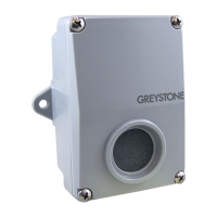
The room CO
2
transmitter device uses a highly accurate and reliable non-
dispersive infrared (NDIR) sensor in an attractive, low prole enclosure for
room applications to monitor CO
2
levels. The sensor uses dual wavelength
optics and LTA (long term adjustment) signal processing technology
to deliver industry leading long-term accuracy and reliability. These
technology features ensure optimum measurement stability for both
periodic and constant occupancy applications, so the device is equally
suitable for the classroom or the hospital room.
Standard features include a eld selectable output signal of either 4-20
mA, 0-5 Vdc or 0-10 Vdc for the highest versatility, programmable CO
2
measurement span, a backlit alpha-numeric LCD and easy menu operation
for conguration.
Optional features include a resistive temperature sensor output (with LCD display of temperature in either
°C or °F), a control relay with programmable setpoint, hysteresis and time delay, and a dry-contact override
switch.
BEFORE INSTALLATION
Read these instructions carefully before installing and commissioning the device. Failure to follow these
instructions may result in product damage. Do not use in an explosive or hazardous environment, with
combustible or ammable gases, as a safety or emergency stop device or in any other application where
failure of the product could result in personal injury. Take electrostatic discharge precautions during
installation. De-energize the power supply prior to installation, this device is intended for indoor air
conditioned spaces, contact factory for other applications. Do not exceed device ratings. This product
is not intended for life-safety applications.
MOUNTING
The transmitter installs directly on a standard electrical box and
should be mounted ve feet from the oor of the area to be
controlled. Do not mount the sensor near doors, opening windows,
supply air diusers or other known disturbances. Avoid areas where
the detector is exposed to vibrations or rapid temperature changes.
Prevent measurement errors by sealing the wall or conduit openings
to prevent air migration from the wall cavity.
The cover is hooked to the base at the top edge and must be removed
from the bottom edge rst. Use a small Phillips screwdriver to loosen
the security screw as shown in Figure 1. Complete removal of the
screw is not required. Use the screwdriver to carefully pry each bottom
corner if necessary. Tip the cover away from the base and sit it aside as
shown in Figure 2.
The PCB must be removed from the base to access the mounting holes.
Follow anti-static procedures when handling the PCB and be careful
not to touch the sensors.
The PCB is removed by pressing the enclosure base to unsnap the
latch near the bottom edge, then the PCB can be lifted out of the base
as shown in Figure 3.
Figure 1
Figure 2
Figure 4
Figure 3
Cover PCB Backplate
IN-GE-CDD4XXXV2-01 02/20 Copyright © Greystone Energy Systems, Inc. All Rights Reserved Phone: +1 506 853 3057 Web: www.greystoneenergy.com
Room Carbon Dioxide Transmitter
CDD4A1 Series - Installation Instructions