Do you have a question about the Grindmaster 3311 and is the answer not in the manual?
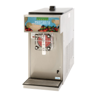
Details on intended uses, product types, and technical specifications for the freezer.
Advice on dispensing beverages and achieving optimal consistency.
Detailed technical data including dimensions, electrical requirements, and capacities.
Instructions for checking the unit upon arrival and handling transit damage.
Guidance on positioning, ventilation, and utility connections for the freezer.
Step-by-step guide on using the freezer, including filling, starting, and dispensing.
Explanation of the 'mix low' indicator and its importance for machine function.
How to modify product thickness using the adjustment screw for optimal texture.
Procedures to safely drain product and rinse the freezer before cleaning.
Detailed instructions for taking apart and cleaning the dispensing valve and dasher assembly.
Procedures for sanitizing the unit and refilling with fresh product post-cleaning.
Method for daily cleaning without full disassembly, following approved procedures.
Routine tasks for daily upkeep to ensure optimal performance and longevity.
Schedule indicating when specific parts require inspection or replacement.
Comprehensive checklist for periodic maintenance every 6 to 12 months.
Instructions for cleaning the condenser and air filters on air-cooled units.
Steps for properly adjusting drive belt tension and pulley alignment.
Electrical schematic for the 115V air-cooled configuration.
Electrical schematic for the 220V air-cooled configuration.
Wiring diagram specific to the water-cooled models.
Specific wiring connections for the compressor on the 115V air-cooled model.
Wiring diagram for the compressor in the 220V air-cooled configuration.
Compressor wiring schematic for the 115V water-cooled unit.
Control logic diagram for the 115V air-cooled Model 3311.
Control logic schematic for the 220V air-cooled Model 3311.
Control logic diagram for the 115V water-cooled Model 3311.
Instructions for connecting the spinner accessory to the 115V electrical box.
Wiring guide for connecting the spinner accessory to the 220V electrical box.
Diagrams and part numbers for the refrigeration components in the 115V air-cooled model.
Component diagrams and identification for the 220V air-cooled refrigeration system.
Part identification and diagrams for the refrigeration system of the 115V water-cooled model.
Schematic illustrating refrigerant flow for AC units (115V & 220V).
Refrigerant flow diagram for the water-cooled model.
| Model | 3311 |
|---|---|
| Power Source | Electric |
| Voltage | 120V |
| Manufacturer | Grindmaster |
| Type | Beverage Dispenser |
| Bowl Capacity | 3 gallons |
| Warranty | 1 year limited |
| Material | Stainless steel |
| Temperature Control | Adjustable Thermostat |