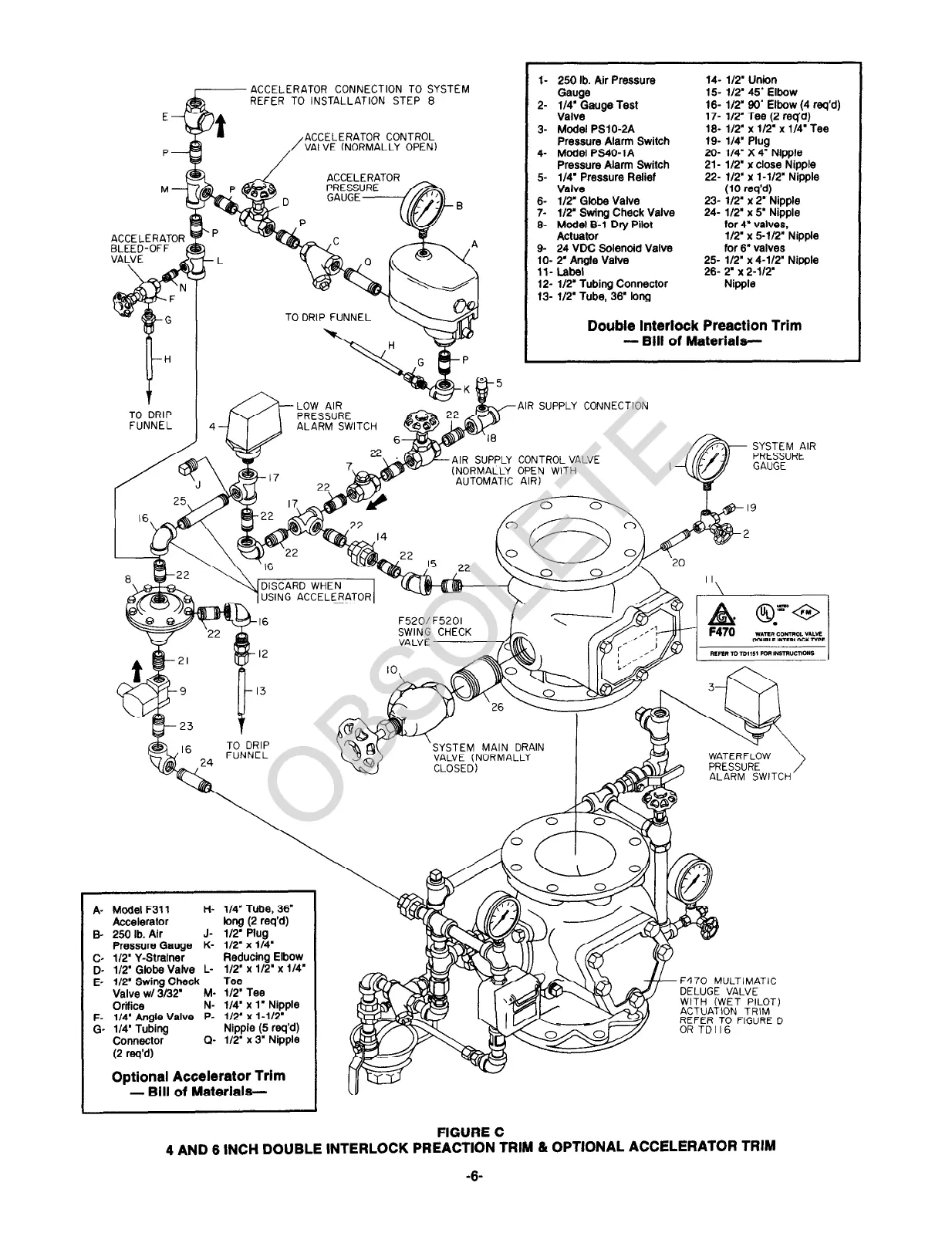
ACCELERATOR CONNECTION TO SYSTEM
REFER TO INSTALLATION STEP 8
E
/
ACCELERATOR CONTROL
P
VALVE (NORMALLY OPEN)
A- Model F311
Ii- l/4’ Tube, 36’
Accelerator
long (2 req’d)
B- 250 lb. Air
J- l/2’ Plug
Pressure Gauge K- 112’ x l/4’
c- 112’ Y-Strainer
Reducing Elbow
Q- l/2’ Globe Vatve L- l/2” x l/2’ x l/4’
E- 112’ Swing Check
Tee
Valve WI 3l32’
M- I/2’ Tee
Orifice
N- l/4’ x I’ Nipple
F- I/4’ Angle Valve P- 112’ x l-1/2’
G- l/4’ Tubing
Nipple (5 req’d)
Connector
Q- 112’ x 3’ Nipple
(2 req’d)
Optional Accelerator Trim
- Bill of Materiaie-
I- 250 lb. Air Pressure
Gauge
2- l/4’ Gauge Test
Valve
3- Model PSIO-2A
Pressure Alarm Switch
4- Model PS40-1A
Pressure Alan Switch
5 l/4’ Pressure Relief
Valve
6- l/2’ Globe Valve
7-
l/2” Swing Check Valve
9
Model B-l Dry Pilot
Actuator
9- 24 VDC Solenoid Valve
IO- T Angle Valve
ll- Label
12- l/2” Tubing Connector
13- l/2’ Tube, 36’ long
14- l/2’ Union
15 I/2’ 45’ Elbow
16- l/2’ 90’ Elbow (4 req’d)
17- l/2’ Tee (2 req’d)
19 l/2’ x l/2’ x l/4’ Tee
19- l/4’ Plug
20- l/C X 4’ Nipple
21- l/2” x close Nipple
22- l/2’ x l-1/2’ Nioole
(10 req’d) ”
23- l/2’ x 2’ Nipple
24- l/2’ x 5’ Nipple
for 4’ valves,
l/2’ x 5-l/2’ Nipple
for 6’ valves
25- l/2’ x 4-W’ Niwle
’ ’
26- 2’ x 2-112’
Nipple
Double interlock Preaction Trim
- Bill of Materiaie-
FIGURE C
4 AND 6 INCH DOUBLE INTERLOCK PREACTION TRIM & OPTIONAL ACCELERATOR TRIM
-6
 Loading...