I- 300 lb. Water
Pressure Gauge
(2 req’d)
2- 114’ Gauge
Test Valve
3- Model Fli30
Manual Control
Station
4- 2’ Angle Vaive
5- l/2’ Ball Valve
(2 req’d)
6- l/2’ Swing Check
Valve
7- l/2’ Spring Loaded
Check Valve
6 Priming Supply
Restriction
9- I/2’ Y-Strainer
lo- Model F793
Automatic Drain
Valve
II- Drip Funnel
supporl Plug
12- Drip Funnel
Support
13- Drip Funnel
14- 3132’ Vent
Fitting
15- I/2’ Angle
Valve
16- I/4’ Tube,
30’ long
17- ll2’Tube
Connector
19 l/2’ Tube,
24’ long
19- l/4’ Plug
20- l/2’ Plug
21- 314” Plug
22- l/2’ Union
(5 w’d)
23- l/2’ 90’ Elbow
(3 req’d)
24- l/2’ Tee (6 req’d)
25- l/2’ x l/4’ x I/2” Tee
(3 req’d)
26- I/2’ x I/2’ x 3l4’ Tee
27- 2’ 90’ Elbow
29 l/2’ x1-112”
Nipple
(17 req’d)
29- l/2’ x 3’
Nipple
30- l/2” x 4” Nipple
31- I/2” x 5’ Nipple
(2 req’d)
32- l/2’ x7-112
Nipple
33- II2 x 10-l/2”
Nipple for
4” valve,
l/2’ x 12’
Nipple for
6’ valve
34- l/4’ x 1 -l/2
Nipple
35- 2 x 3
Nipple
(2 req’d)
13
21
‘CTION \
26
ALARM CONTROL VALVE *
(NORMALLY OPEN)
26
25
ALARM TEST 16
LLY CLOSED)
‘DIAPHRAGM CHAMBER
PRESSURE GAUGE
TO DRIP FUNNE
MANUAL CONTROL STATION
TO DRIP FUNNEL
DIAPHRAGM CHAMBER
SUPPLY CONTROL VALVE
(NORMALLY OPEN)
26
23
ul
‘DIAPHRAGM CHAMBER
SUPPLY CONNECTION
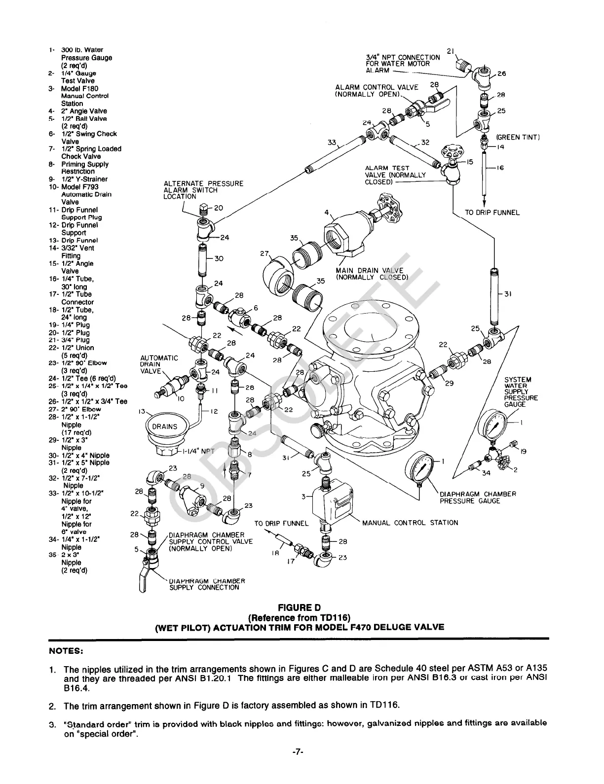
FIGURE D
(Reference from TD116)
(WET PILOT) ACTUATION TRIM FOR MODEL F470 DELUGE VALVE
NOTES:
1. The nipples utilized in the trim arrangements shown in Figures C and D are Schedule 40 steel per ASTM A53 or Al35
and they are threaded per ANSI B1.20.1
The fittings are either malleable iron per ANSI 816.3 or cast iron per ANSI
816.4.
2. The trim arrangement shown in Figure D is factory assembled as shown in TD116.
3. “Standard order” trim is provided with black nipples and fittings: however, galvanized nipples and fittings are available
on “special order”.
-7-
 Loading...