EasyManua.ls Logo

Grizzly T20551 User Manual

Grizzly T20551
2 pages
To Next Page IconTo Next Page
Page #1 background imageLoading...
Page #1 background image








  




 
 








Model T20551
Magnetic Switch Instruction Sheet
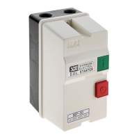
MAGNETIC
SWITCH
ASSEMBLY
Contactor
SHENDIAN
MA-30
(220V Coil)
Thermal
Overload Relay
SHENDIAN
RA-30
(22-34A)












IMPORTANT: This magnetic switch toggles a motor ON and OFF, and helps
provide thermal overload protection for the motor if operating temperature
gradually increases due to heavy work loads. The thermal overload relay inside
is not designed to cut power in the event of a sudden motor overload or stall.
To help protect a motor from this type of overload, this magnetic switch MUST be connected to a properly sized
power supply circuit with a correct fuse or circuit breaker.
OPERATION: The green push button switch allows current to go to the magnetic coil which pulls the contactor
closed. Main current now passes through the thermal overload relay and then to the motor. This relay monitors
motor current draw. If the motor begins to overheat, this relay breaks the magnetic field, which opens the
contactor and cuts current to the motor. The red push button breaks the magnetic field, which opens the
contactor and disconnects the current to the motor.
Electrocution or fire could occur if this switch is
not installed by a qualified electrician!
Question and Answer IconNeed help?

Do you have a question about the Grizzly T20551 and is the answer not in the manual?

Grizzly T20551 Specifications

General IconGeneral
BrandGrizzly
ModelT20551
CategorySwitch
LanguageEnglish

Summary

Safety Warning

Electrocution Hazard

Warning about potential electrocution or fire if the switch is not installed by a qualified electrician.

Magnetic Switch Assembly Components

Contactor and Thermal Overload Relay

Identifies the Contactor MA-30 (220V Coil) and Thermal Overload Relay RA-30 (22-34A) within the assembly.

Key Operational Information

Provides crucial details on the switch's function, overload protection, and connection requirements.

Control Features and Operation

Thermal Relay Amp Adjustment

Instructions for adjusting the thermal overload relay amp setting based on motor specifications.

Manual Operation Controls

Details on the Manual Trip Test Lever, Manual Contactor Override Lug, ON Button, and Reset/OFF Button.

Parts Breakdown