T28170 Tool Stand (Mfd. Since 10/17)
-3-
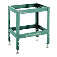
5. Attach (4) foot brackets to inside of legs
with (16) M8-1.25 x 20 carriage bolts and
(16) M8-1.25 flange nuts (see Figure 6).
Make sure bottom of foot brackets are even
with bottom of legs.
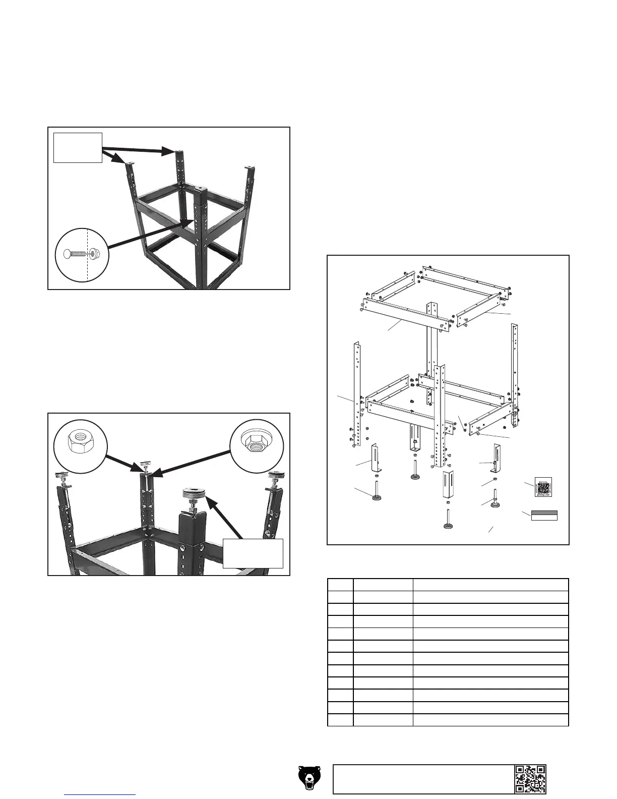
Parts Breakdown & List
T28170
NOTICE
DO NOT exceed maximum
weight capacity of 400 lbs.
grizzly.com
5
1
2
3
4
6
7
8
9
10
11
12
9
REF PART # DESCRIPTION
1 PT28170001 ADJUSTABLE FOOT M12-1.75 X 120
2 PT28170002 FOOT BRACKET
3 PT28170003 LEG
4 PT28170004 SIDE SUPPORT
5 PT28170005 END SUPPORT
6 PT28170006 CARRIAGE BOLT M8-1.25 X 20
7 PT28170007 FLANGE NUT M8-1.25
8 PT28170008 FLANGE NUT M12-1.75
9 PT28170009 HEX NUT M12-1.75
10 PT28170010 GRIZZLY.COM LABEL
11 PT28170011 WEIGHT CAPACITY NOTICE LABEL
12 PT28170012 QR CODE LABEL
BUY PARTS ONLINE AT GRIZZLY.COM!
Scan QR code to visit our Parts Store.
1. Place tool stand on flat surface.
2. Loosen (4) M12-1.75 hex nuts on tool stand
feet.
3. Lay a level across tool stand from side-to-
side and end-to-end.
4. Adjust tool stand feet to make sure level lays
flat at both positions.
5. Tighten hex nuts to secure tool stand feet.
Leveling Tool Stand
6. Thread (4) M12-1.75 hex nuts onto (4) adjust-
able feet (see Figure 7).
7. Thread (4) adjustable feet into foot brackets
and secure with M12-1.75 flange nuts (see
Figure 7).
8. Turn tool stand upright.
Figure 6. Foot brackets attached.
x 16
Foot
Brackets
Figure 7. Adjustable feet attached.
Adjustable
Foot
x 4
x 4
 Loading...