Do you have a question about the Grohe EUROSMART COSMOPOLITAN E and is the answer not in the manual?
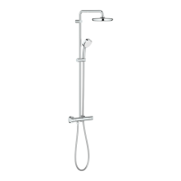
Minimum, operating, recommended, and test pressure values.
Maximum operating and recommended energy-saving temperatures.
Installation must be in frost-free rooms; power supply for indoor use only.
Use only genuine parts; other parts void warranty and CE marking.
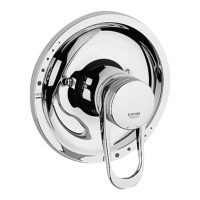
Prepare wall, observe depth, align and mark mounting box.
Connect pipes, close isolating valve, attach hose with filter.
Electrical work by qualified electrician only; use round cables 6-8.5mm.
Cut opening, insert cable, connect wires, secure terminal and lid.
Attach structural shell protection before tiling is completed.
Consider 1-3mm grouting joint relative to protection cover.
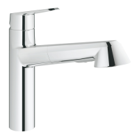
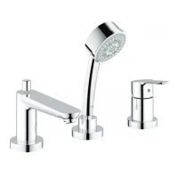
| Product Type | Bathroom Faucet |
|---|---|
| Material | Brass |
| Finish | Chrome |
| Installation Type | Deck mounted |
| Power Supply | Not applicable |
| Water Connection | 1/2 inch |
| Infrared Sensor | No |
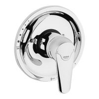
| Adjustable Temperature Limiter | Yes |
| Automatic Flushing | No |
| Safety Shut-Off | Yes |
| GROHE StarLight finish | Yes |
| GROHE EcoJoy technology | Yes |
| Holes Required | 1 |
| Spout Type | Fixed Spout |