1
English
Application
Thermostat mixers are designed for use with hot water
supplied from pressurized storage heaters and offer the
highest temperature accuracy when used in this way. Given
sufficient output (min.18 kW or 250 kcal per min), electric or
gas-fired instantaneous heaters are also suitable.
Thermostat mixers cannot be used in conjunction with low-
pressure storage heaters (displacement water heaters).
All thermostat mixers are adjusted at the factory at a flow
pressure of 45 psi on both sides.
If temperature deviations should exist due to special
installation conditions, then the thermostat is to be adjusted to
the local conditions (see Adjustment).
Specifications
Minimum flow pressure without
downstream resistances 7.25 psi
Minimum flow pressure with
downstream resistances 14.5 psi
Max. operating pressure 145 psi
Recommended flow pressure 14.5 psi - 72.5 psi
Test pressure 232 psi
Flow rate: approx. 13 L/min or 3.5 gpm/20 psi
approx. 20 L/min or 5.3 gpm/45 psi
approx. 30 L/min or 8.0 gpm/100 psi
Max. water temperature at hot water inlet 176 °F
Temperature range adjustable on
the scale marked handle 70 - 115 °F
safety stop 100 °F
Hot water temperature at supply connection 4 °F higher than
mixed water temperature.
Cold water connection = right
Hot water connection = left
Minimum flow rate 1.3 gpm
At a flow pressure over 72.5 psi it is recommended that a
pressure reducing valve be fitted in the supply line.
Installation
Flush pipes thoroughly.
Wall installation
1. Install S-unions and attach the sleeve together with the
escutcheon, see fold-out page I, Fig. [1].
2. Screw-mount the mixer.
3. Push the sleeve with escutcheon onto the union nut.
4. Open isolating valves (X) and check connections for
watertightness.
5. Screw the escutcheon flush against the wall.
Refer to the dimensional drawing on fold-out page I.
The projection can be increased by 30mm with an extension,
(see Replacement Parts, fold-out page II, Prod. no.: 46 238).
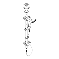
Adjusting
For temperature adjustment, see Figs. [2] and [3].
1. Open the shut-off valve and check the temperature of the
water with a thermometer, see Fig. [2].
2. Lever out cap (A), see Fig. [3].
3. Remove screw (B).
4. Detach temperature control handle (C).
5. Turn regulating nut (D) until the water temperature has
reached 100 °F.
6. Install temperature control handle (C) so that button (E)
points towards the front, see Fig. [2].
7. Screw in screw (B), see Fig. [3].
8. Refit cap (A).
Temperature limitation
The safety stop limits the temperature range to 100 °F.
The 100 °F limit can be overridden by pressing the button (E).
Shut-off handle (F) operation, see Fig. [2].
Shut-off handle in central position = closed
Turn shut-off handle anti-clockwise = discharge from spout
Turn shut-off handle clockwise = discharge from shower
Prevention of frost damage
When the domestic water system is drained, thermostats must
be drained separately, since non-return valves are installed in
the hot and cold water connections. For this purpose, the
mixer must be removed from the wall.
Maintenance
Inspect and clean all parts, replace if necessary and lubricate
with special grease (Prod. no. 18 012).
Shut off cold and hot water supplies by closing both
isolation valves (X), see fold-out page I fig. [4].
I. Non-return valve (H) or (J), see fold-out page I Fig. [5].
• Remove connection nipple (K) by turning clockwise (left-
hand thread) using a 12mm allen key.
Install in reverse order.
II. Thermostatic compact cartridge (L), see fold-out
page III, Fig. [6].
• Remove O-ring (M1).
• Loosen screw ring (M) using a 34mm tool.
• If necessary, lever out thermostatic compact cartridge (L) via
recess (L1).
• Remove screw ring (M).
Install in reverse order.
Observe the correct installation position of the
thermostatic compact cartridge (L) and the scale ring (N),
see details, Fig. [6].
Readjustment is necessary after every maintenance
operation on the thermostatic compact cartridge
(see Adjusting).
III. Aquadimmer (O), see fold-out page III, Figs. [7] and [8].
Install in reverse order.
Observe correct installation position of individual
components, see details.
IV. Unscrew and clean mousseur (13 939), see fold-out
page II.
Install in reverse order.
Replacement parts, see fold-out page II (* = special
accessories).
Care
Instructions for care of this faucet will be found in the Limited
Warranty supplement.
 Loading...