3
Approval and conformity
The conformity declarations can be obtained from the following
address:
GROHE Deutschland Vertriebs GmbH
Zur Porta 9
D-32457 Porta Westfalica
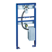
Rough installation
During installation, please note
• The control unit must be easy to access for maintenance
work.
• The cold water supply must be connected on the left and the
hot water supply on the right.
Panelling wall installation, see fold-out page II, Figs. [3-14].
Installation inside a stud partition, see fold-out page III,
Figs. [15 - 22].
Installation
Water connection
Do not solder the connections between the pipe and
housing, otherwise the built-in isolating valve may be
damaged.
1. Insert and fasten stud bolt (A) for attaching the wash basin
in accordance with the wash basin dimensions, see fold-out
page III, Fig. [23].
2. Fasten the elbow union and retaining plate to the uppermost
crossrail, see Fig. [24].
3. Ensure accessibility of the cable through the inspection
chamber, see Fig. [25].
4. Connect water supply line (B), see fold-out page IV, Fig. [26].
5. Open hot and cold water supply and check that connections
are watertight. Flush pipes thoroughly before and after
installation (observe EN 806).
Caution: the water must be directed from the spout into the
room during flushing.
Close the isolating valve, see Fig. [27].
6. Connect thermostat unit (D) with filter (D1) to hot water
isolating valve (C), see Fig. [28].
7. Screw elbow (F) with filter (F1) hand-tight to cold water
isolating valve (E), see Fig. [29].
8. Connect elbow (F) with seal (G) to the thermostat unit (D).
9. Fasten elbow (F) to thermostat unit (D) and isolating
valve (E).
Electrical installation
Electrical installation work must only be
performed by a qualified electrician. This work
must be carried out in accordance with the
regulations according to IEC 364-7-701-1984
(corresponding to VDE 0100 Part 701) as well
as all national and local regulations.
• Only round cables with max. outside diameter 6 to 8.5mm
may be used.
• The voltage supply must be separately switchable.
1. Connect the earth wire, see fold-out page IV, Fig. [30].
2. Insert 230V connecting wire (H) into the transformer
base (J) and insulate.
3. Pull sleeve (K1) over the two current-carrying wires (H1).
4. Attach lustre terminal (K); observe assignment,
see Fig. [31].
5. Secure all three wires with cable tie (K2), just in front of
lustre terminal (K).
6. Route cable (H2) in an arc and position lustre terminal (K)
on the locators in transformer base (J), see Fig. [32].
7. Secure cable (H) using screws (L) and strain relief (M).
8. Fasten lid (N) in base (J) using screw (O).
9. Install the structural shell protection, see Fig. [32].
Further installation
1. Predrill both plaster fibre / plasterboards in accordance with
fold-out page I, Fig. [1].
2. Screw both plaster fibre / plasterboards in front of the
element, see Fig. [34].
Note for installer:
• Do not carry out any further installation procedures until the
tiling is completed.
Note for tiler:
• Do not obstruct the inspection aperture for maintenance
work, use tile frame (Q) (special accessory: 37 002),
see Fig. [34].
Performing final installation.
Further installation procedures are explained in the final
installation.
Prevention of frost damage
When the domestic water system is drained, the thermostats
must be drained separately since non-return valves are
installed in the hot and cold water connections.
For this purpose, the thermostat must be removed from the
unions.
Replacement parts, see fold-out page I ( * = special
accessories).
This product conforms to the requirements of the
relevant EU guidelines.
 Loading...