8
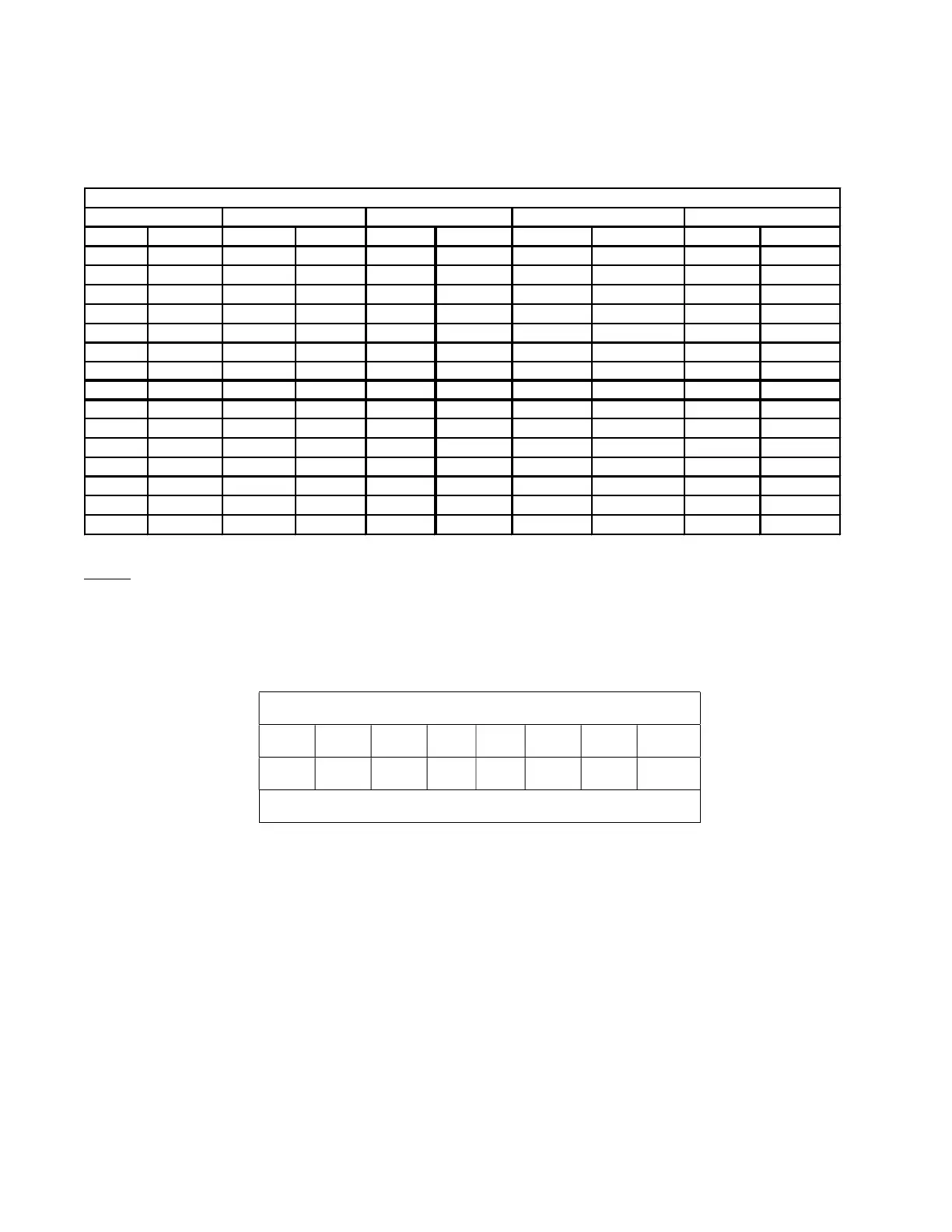
TABLE 4 – FLOW CAPACITY SETTING
Table 4 shows flow capacity for a regulator set at 100% full open. Unless otherwise specified, the orifice selector sleeve [12] is
factory set at the 100% full open position.
* Orifice sleeve installed in 100% flow capacity position.
NOTE: Flow capacity values are in SCFH. For NCMH, multiply the listed capacities by 0.029
If reduced capacity is specified on an order, the sleeve is set at the appropriate restriction. Actual capacity at any other position
can be calculated by multiplying the capacity value from Table 4 for a specific pressure by the decimal value from Table 5.
TABLE 5 – ORIFICE SLEEVE POSITION
ORIFICE SLEEVE POSITION
1 2 3 4 5 6 7 8
1.0 0.75 0.50 0.25 0.20 0.15 0.10 0.05
FLOW CAPACITY MULTIPLIER
1/2" Models are only available with positions 1, 2, 3, and 4
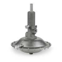
BLANKETING THE TANK
Before installing a new or replacement regulator, the tank pressure must be below the desired set pressure so the regulator setting
can be verified. Sequentially open the block valves in the following order: (1) Sense Line, (2) Regulator Discharge Line and (3)
Regulator Supply (See Figure 3).
If the regulator was set at the factory, blanket gas will begin to flow immediately. The tank pressure must be monitored closely to
verify that the gas flow shuts off at the set pressure.
If the regulator was not set at the factory, make sure that the adjusting screw [11] is backed out as far as possible (no spring
compression). When the blanket gas supply valve is turned on, there will be no flow, unless the tank pressure is very low. Now
slowly turn the adjusting screw to increase tank pressure and the gas will begin to flow. The tank pressure can be increased as
gradually as desired until the correct pressure setting is attained. When tank pressure is reached, back out adjusting screw, if
necessary, until gas flow stops.
WARNING: In the event of an actuator diaphragm [42] or piston diaphragm [36] failure, the regulator will fail in the open
position. Gas flow will NOT be shut off. Emergency and or pressure/vacuum relief valves must be sized to include
blanket gas regulator capacity in addition to normal and emergency venting requirements.
PSIG BARG 1/2" 1" 1/2" 1" 1/2" 1" 1/2" 1"
5 0.34 2160 4600 2810 5800 3660 7400 2800 5700
10 0.69 3250 7100 4230 8800 5490 11300 4190 8700
15 1.03 4370 9200 5690 11500 7390 14600 5630 11300
20 1.38 5130 11200 6680 14000 8680 17900 6610 13800
30 2.07 6630 15100 8630 18900 11210 24000 8540 18600
40 2.76 8140 18800 10590 23600 13760 30000 10480 23200
50 3.45 9650 22500 12560 28200 16320 35800 12430 27700
60 4.14 11160 26000 14520 32600 18860 41500 14370 32100
80 5.52 14180 33000 18440 41300 23950 52600 18250 40700
100 6.89 17200 40000 22370 50100 29060 63700 22140 49300
120 8.27 20210 47000 26290 58800 34150 74800 26020 57900
140 9.65 23230 53900 30220 67500 39250 85900 29910 66500
160 11 26240 60900 34140 76300 44340 97000 33790 75100
180 12.4 29260 67900 38060 85000 49440 108100 37680 83700
200 13.8 32280 74900 41990 93700 54540 119200 41560 92300
FLOW CAPACITY (SCFH) *
Supply Pressure AIRCarbon Dioxide Nitrogen Natural Gas 0.55 S.G.