WWW.GFWORLDWIDE.COM | +1 (208) 664-9291
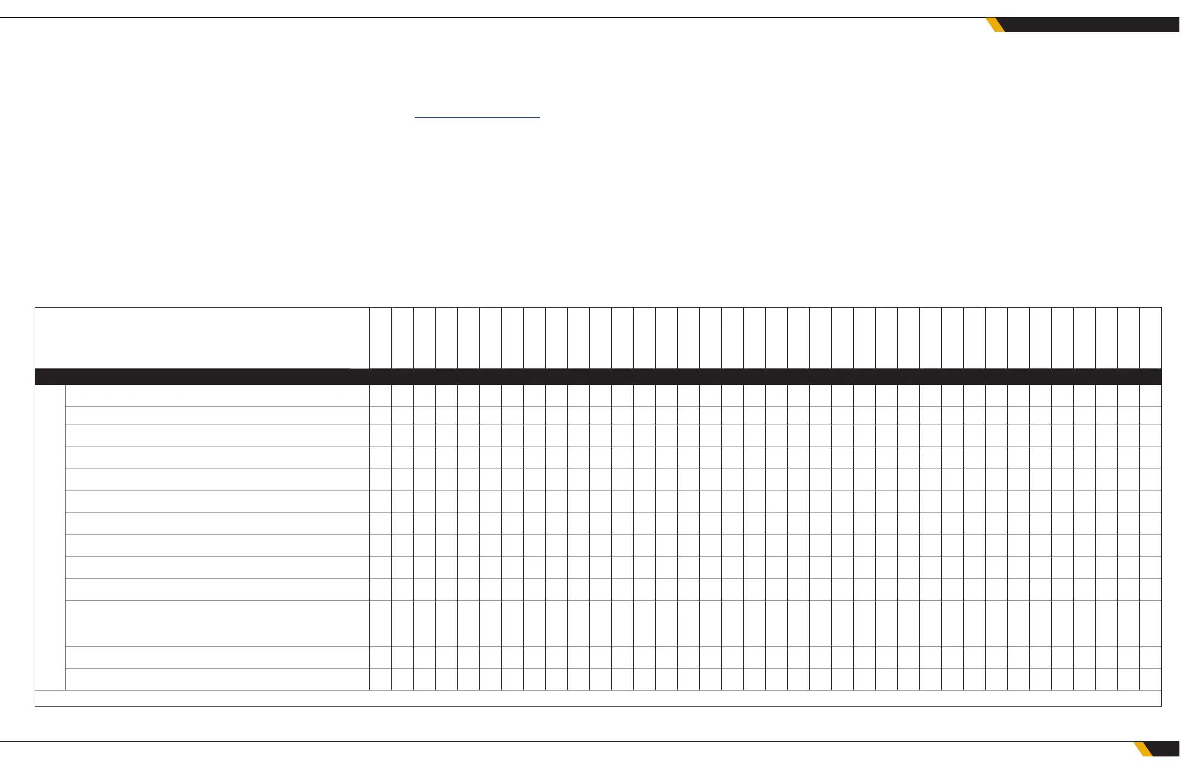
MAINTENANCE LOG
DATE ▼
DAILY MAINTENANCE SCHEDULE
DAILY
VISUALLY INSPECT
• HYDRAULIC FLUID LEVEL
• BODY MOUNTS
• REAR BODY PINS
• TANK MOUNTS
• PUMP MOUNTING BOLTS
• CHECK HOSES AND FITTINGS FOR LEAKS
• HOSES AND WIRING HARNESSES ARE SECURED
• FLUID LEVELS FOR AUX HEATER FUEL AND EXPANSION TANK
VERIFY HYDRAULIC CONTROL VALVES OPERATE PROPERLY
VERIFY SAFETY EQUIPMENT IS PRESENT AND FUNCTIONAL
INCLUDING EMERGENCY STOP SWITCHES, WHEEL CHOCKS AND
FIRE EXTINGUISHERS
VERIFY PROPER OPERATION OF ALL VALVES
VERIFY PROPER OPERATION OF THE AUXILIARY HEATING SYSTEM
*NOTE: FREQUENCY MAY VARY DEPENDING ON NEED. IT IS THE USER'S RESPONSIBILITY TO ESTABLISH APPROPRIATE SERVICE INTERVALS.
6.1 OVERVIEW
Maintaining your equipment will help prevent breakdowns and greatly
extend the service life of your Ground Force equipment. It is a fairly simple
process to maintain uid levels, change uids and lters when scheduled,
and monitor and tighten bolts or ttings that have worked loose.
6.2 MAINTENANCE SCHEDULES
Maintenance schedules are provided, including sample maintenance logs.
This will help with scheduling and tracking of maintenance.
6.3 VENDOR-SUPPLIED COMPONENTS
See the manufacturer's manual for maintenance, safety and operation infor-
mation for all non-Ground Force components. To request manufacturer's
manuals, contact Ground Force Technical support to request by writing to
service@gfworldwide.com.
6.4 OIL COOLER
If leaks develop in the oil to water cooler, it is possible for the hydraulic oil
to mix with the water. Observe the main hydraulic tank for signs of water
ingress or loss of hydraulic uid.
Inspect the seal by draining water in a bucket and looking for oil in the water
when putting into service after winter storage.
The oil-to-water cooler must be winterized or the water will freeze and dam-
age the cooler. Drain the water out of the cooler when freezing conditions
are possible by opening the drain valve and purging all water from the
cooler. Compressed air may be used to force water out of the cooler and
into the pump volute.
After blowing the water out, close the drain valve but leave the supply and
shutoff valves open to avoid trapping residual moisture.
39
MAINTENANCE SCHEDULES
 Loading...