The entire APX 5.0-30.0P-S2 high-voltage energy storage system is composed of a APX
98034-P2 (hereinafter referred to as Power Module) and multiple APX 5.0P-B1 battery
modules (hereinafter referred to as Battery Module, the maximum number of Battery
Module connected in parallel is 6).
Each Battery Module consists of 100Ah LFP battery cells and a DC-DC converter, which
boosts a power source of 51.2V up to 380V. One to six Battery Modules can be connected
in parallel to increase the capacity and power of the energy storage system.
The APX battery system powers the loads through the three-phase hybrid inverter MOD
3-10KTL3-XH (Backup version) or MID 11-30KTL3-XH whenever demanded; when solar
becomes available during daytime, solar energy powers the loads as a priority and the
surplus solar power is stored into the APX battery system.
1 Product Overview
1.1 Intended Use
1
2
1.2 Appearance
1.2.1 APX 98034-P2(Power Module)
Power Module is composed of Power control units, relay, fuse, DC switch, power supply
and communication terminals. The appearance of the product is shown as below.
Turn on/off the power connection from Power
Module to hybrid Inverter
Provide overcurrent protection for a circuit
Ground terminal, connect to the hybrid inverter
APX system parallel communication output port
Ground terminal, connect to the Battery Module
APX system parallel communication input port
The positive output from APX system to the hybrid
inverter
The neutral output from APX system to the hybrid
inverter
The negative output from APX system to the hybrid
inverter
Port for communication with the hybrid inverter
Communication with the Battery Module
Connect to the positive power terminal of the
Battery Module
Connect to the negative power terminal of the
Battery Module
USB port, connect to a USB flash drive to upgrade
firmware
Provide protection against excessive pressure
Wake up the Battery Module (Press and hold for
over 5 seconds)
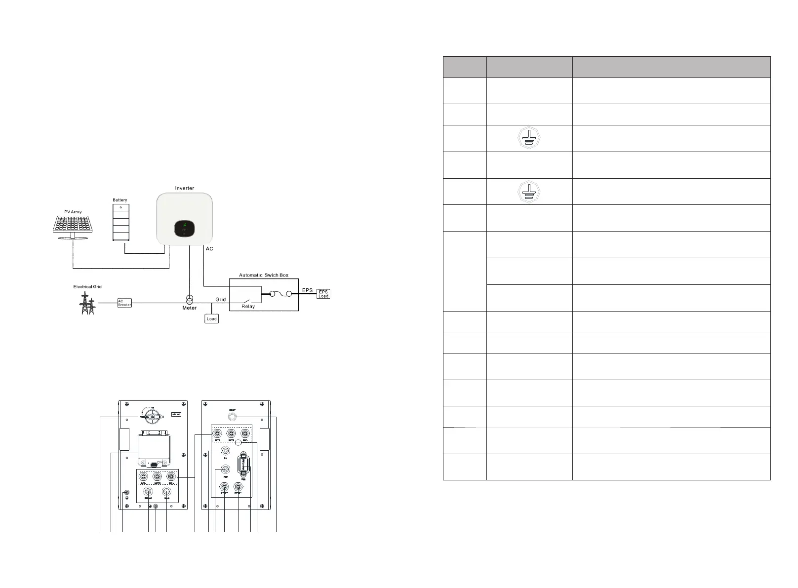
Figure 1-1: System diagram of APX High voltage battery system
Figure 1-2: Schematic diagram of power panel
1 2 3 4 5 6 7 8 9 10 11 12 13 14
Fuse
 Loading...