English (GB)
3
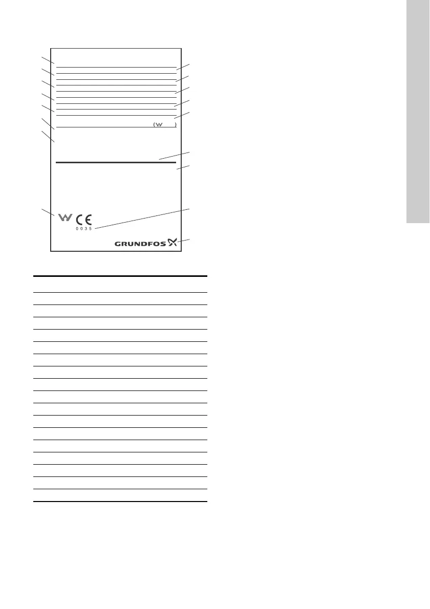
3. Nameplate
Fig. 2 Example of nameplate
4. Installation
Before installation, check the following:
• Do the specifications of the GT tank correspond
to the order?
• Are all visible parts intact?
• Is the maximum system pressure lower or equal
to the maximum operating pressure for the GT
tank? See tank nameplate.
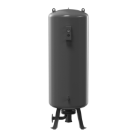
4.1 Lifting the tank
The top of large tanks has a welded-on flange/nut in
which a lifting eye can be fitted. When the tank is in
place and secured to the floor, the lifting eye can be
removed.
4.2 Location
Always install the GT tank in the discharge pipe as
close to the pump as possible.
Install the GT tank in a frost-free room. It must be
possible to inspect the GT tank from all sides.
The air-filling valve, water shut-off and discharge
must be accessible, and the nameplate must be
visible.
Install the GT tank so that it is not stressed by the
pipework. If vibrations are likely to occur, we
recommend that the GT tank is installed so that
vibrations are absorbed.
We recommend to follow these steps:
1. Lift and position the GT tank.
2. Level as required (horizontally and vertically).
3. Secure the GT tank.
4. Connect the pipes and fittings.
5. Check/adjust the precharge pressure.
6. Start the pump or application.
No additional loads from the piping system or
equipment are allowed.
TM05 5792 4012
Pos. Description
1 Product number
2 Model number
3 Max. working pressure
4 Factory-set precharge pressure
5 Total tank volume
6 Production code (year and week)
7 Serial number
8 Marking
9 Manufacturer
10 Notified body
11 Adjustment of precharge pressure
12 Production site
13 Max. working temperature
14 Thread connection
15 Test pressure
16 Configuration code
17 Type designation
Precharge Instructions:
1. Turn the power and water supply off, then turn on a tap to drain the tank before
adjusting precharge.
2. For a pressure switch controlled pump with a differential set up to 30 psi (2.0 bar),
the precharge should be set to 2 psi (0.2 bar) below the cut-in pressure.
3. For a pump controlled by a pressure switch with a pressure differential
greater than 30 psi (2.0 bar), electronic controls or variable speed controls,
the tank precharge should be set to 65% of cut-out or max system pressure.
4. For pressure tanks installed on main pressure, the tank precharge should be set
equal to the main pressure.
5. For hot water expansion applications, the tank precharge should be set equal to
the system ¿ ll pressure or the main pressure.
Serial Number
Global Water Solutions Ltd. Production Site: TankPAC Industries
L60LH-14-1
Factory Precharge:
Test Pressure:
Max. Temperature: TS
Connection:
Nominal Volume:
Prod. Year/Week:
Part Number:
Type:
Max. Working Pressure: PS
Con¿ g:
Model Number:
Made in Taiwan
Water Mark
ATS5200.485
AGA 60044
COLD WATER
APPLICATIONS
1
2
3
4
5
6
7
17
16
15
14
13
12
11
10
9
8
 Loading...