English (GB)
6
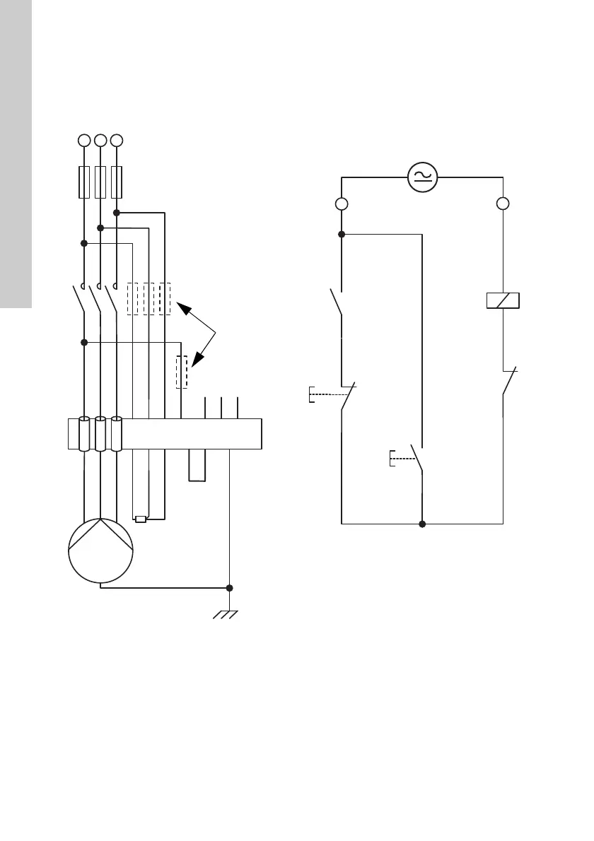
Three-phase system
The wiring diagram shows an example of a three-
phase pump with insulation measurement.
The connections to L1, L2, L3 and "5" can be made
with a cable of up to 10 mm
2
. A special fuse unit up
to approximately 50 A is therefore not required.
If larger backup fuses are used, the voltage to the
L1, L2 and L3 must be protected separately. We
recommend a maximum of 10 A or less.
Fig. 1 Three-phase connection
TM03 0122 2205
1
2
35
46
13
14
S1
K1
S0
22
21
13
14
K1
96
95
E1
K1
A1
A2
L
1
L
2
L
3
3
~
Pt100
E1
L1
L2
L3
+
C
C
I1
I2
I3
T1
T2
FE
5
A
Y
B

 Loading...
