Do you have a question about the Grundig GHP-MM08 and is the answer not in the manual?
Details unit models, capacities, and visual features.
Lists different factory models and their corresponding unit capacities and specifications.
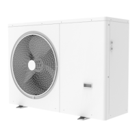
Shows images of the unit appearance for different capacity ranges.
Illustrates internal component placement for various models.
Visual representation of the refrigerant and water piping system.
Depicts refrigerant flow during heating, cooling, and defrosting operations.
Explains shutdown, standby operations, and crankcase heater control.
Describes the process and delays for compressor startup.
Outlines component control during heating, cooling, and DHW modes.
Covers safety features like pressure, temperature, and current protection.
Explains oil return and defrosting operations.
Details the function and location of various temperature sensors.
Provides a table of adjustable parameters for system configuration.
Shows the electrical connections for the unit's components.
Identifies main components within the electric control box.
Describes the types and locations of printed circuit boards (PCBs).
Lists error codes, their descriptions, and remarks for troubleshooting.
Crucial safety warnings before performing any troubleshooting procedures.
Analyzes and provides solutions for error code P01.
Analyzes and provides solutions for error code P02.
Analyzes and provides solutions for error code P03.
Analyzes and provides solutions for error code P04.
Analyzes and provides solutions for error code P05.
Analyzes and provides solutions for error code P06.
Analyzes and provides solutions for error code P07.
Analyzes and provides solutions for error code P08.
Analyzes and provides solutions for error code P10.
Analyzes and provides solutions for error code P11.
Analyzes and provides solutions for error code P13.
Analyzes and provides solutions for error code P21.
Analyzes and provides solutions for error code P25.
Analyzes and provides solutions for error code E01.
Analyzes and provides solutions for temperature sensor errors E02 to E09.
Analyzes and provides solutions for error code E10.
Analyzes and provides solutions for error code E14.
Troubleshooting for inverter module errors for single-phase models.
Analyzes and provides solutions for PFC module errors E19, E24, E27.
Analyzes and provides solutions for compressor startup errors E20, E21.
Analyzes and provides solutions for error code E25.
Analyzes and provides solutions for error code E26.
Analyzes and provides solutions for error code E28.
Analyzes and provides solutions for error code E34.
Explains non-error codes related to inverter module specific actions.
Provides resistance values for various temperature sensors at different temperatures.