EasyManua.ls Logo

GSI Group Agri-Alert 128 Touch - User Manual

GSI Group Agri-Alert 128 Touch
90 pages
Print Icon
To Next Page IconTo Next Page
Loading...
A BRAND OF
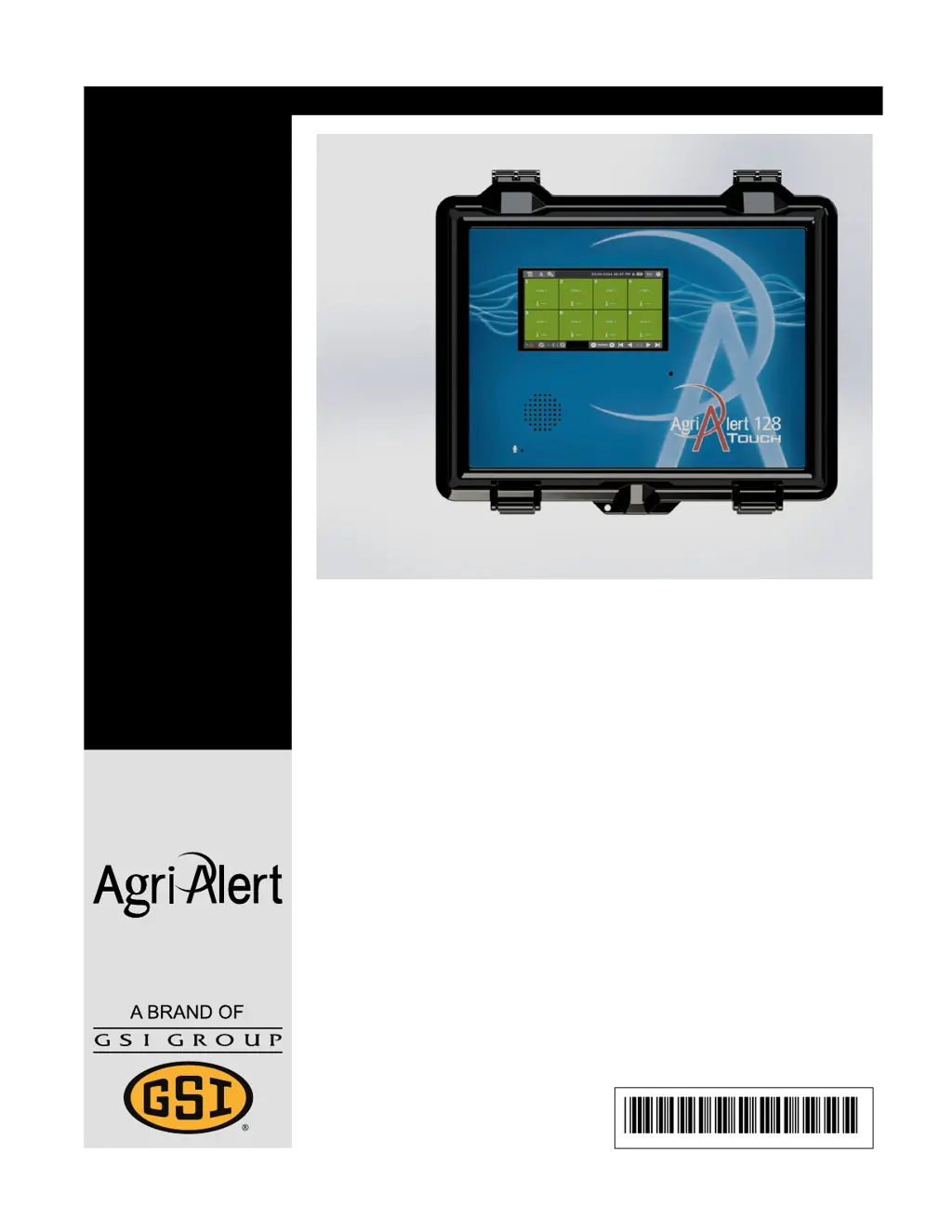
Agri-Alert 128 Touch
Models:
ALERT SYSTEM
890–00583
User Guide
895–00677
Version 00
895–00677

Table of Contents

Other manuals for GSI Group Agri-Alert 128 Touch

Questions and Answers

  • W
    William EspinozaSep 23, 2025
    Why can't my GSI Group Industrial Equipment recognize my password over the phone?
    • A
      Alexander JamesSep 23, 2025
      If the AA128 Touch of your GSI Group Industrial Equipment does not recognize your selection over the phone, try typing your choice slower (leave about 1/2 seconds between each key). This may be due to phone compatibility issues.
  • J
    Jared WilsonAug 25, 2025
    Why does my GSI Group Agri-Alert 128 Touch Industrial Equipment shut down when I unplug it?
    • T
      Tanner GilmoreAug 25, 2025
      If your GSI Group Industrial Equipment system shuts down when you unplug it from the main sector, ensure the battery is correctly connected. Allow the system to recharge the battery for about 3.5 hours. Also, verify that the loads connected to the siren output, 12VDC output, 28 VDC output, and SBI power output do not exceed the circuit capacity. If the problem persists, contact your dealer.
  • T
    Troy FullerAug 25, 2025
    How to fix a siren that doesn't work on GSI Group Agri-Alert 128 Touch?
    • C
      christinagillAug 26, 2025
      If the siren on your GSI Group Industrial Equipment isn’t working, first ensure that the siren load does not exceed the circuit capacity. If no siren is connected to the siren terminals, connect a 1.5kΩ, ½ W resistor in its place, or disable the siren output. If the siren impedance is too high, add a 1,5K ?, ½W resistor to the siren circuit, as close to the siren as possible. Also, check if the siren wire or the siren itself may be defective. If the problem persists, contact your dealer.
  • M
    Michele KellyAug 27, 2025
    Why does my GSI Group Agri-Alert 128 Touch refuse to arm?
    • S
      Seth HesterAug 27, 2025
      If your GSI Group Industrial Equipment system refuses to arm, first ensure that an intrusion zone is programmed and that there is no active alarm in any intrusion zone. Also, ensure you are logged in with the installer or master password. If the problem continues, contact your dealer.
  • D
    Donna DiazAug 27, 2025
    What to do if GSI Group Industrial Equipment does not detect any probe?
    • C
      Carrie SalazarAug 27, 2025
      If the system does not detect any probe, make sure the flat cable between the top and the bottom board inside the enclosure is properly connected. Also, ensure that the removable terminal block is properly inserted on the bottom board. Check the wiring of the zone inputs. If the problem continues, contact your dealer.
  • R
    rdurhamSep 13, 2025
    What should I do if the 12 volt auxiliary is disconnected on my GSI Group Agri-Alert 128 Touch Industrial Equipment?
    • J
      Joe WilsonSep 13, 2025
      If the 12 volt auxiliary is disconnected in your GSI Group Industrial Equipment, make sure the load connected to the 12VDC output does not exceed the circuit capacity. Check the wiring of the 12VDC output and verify if the fuse F29 or F30 is not opened.
  • M
    Mary DaviesSep 12, 2025
    Why does my GSI Group Industrial Equipment system refuse to arm?
    • A
      Alyssa MorenoSep 12, 2025
      If the GSI Group Industrial Equipment system refuses to arm, make sure an intrusion zone is programmed and that there is no active alarm in any intrusion zone. Also, log in with the installer or master password.
  • E
    Emma CisnerosSep 12, 2025
    How to troubleshoot a disconnected 28 volt auxiliary in GSI Group Agri-Alert 128 Touch Industrial Equipment?
    • T
      taylorsusanSep 12, 2025
      If the 28 volt auxiliary is disconnected in your GSI Group Industrial Equipment, ensure the 28VDC does not exceed the circuit capacity. Check the main sector to the AA128 Touch and wiring. Verify if the fuse F31 or F32 is not opened. Use a voltmeter to check voltage at the AA128 Touch supply input terminals (24Vdc minimum at J13 between VDC+ and VDC-).
  • T
    Theresa JohnsonSep 4, 2025
    Why GSI Group Industrial Equipment doesn't start when I plug in the battery?
    • J
      Joe CampbellSep 4, 2025
      On first startup of GSI Group Industrial Equipment, the controller needs to be powered by the main sector.
  • B
    Brad AvilaSep 2, 2025
    What to do if the disconnected line icon is displayed on GSI Group Industrial Equipment?
    • A
      Anthony WilsonSep 2, 2025
      If the disconnected line icon is displayed on your GSI Group Industrial Equipment, ensure the entry line is plugged into the correct phone jack of the phone plug-in card and that the plug-in card is properly inserted in the "PHONE CARD" connector. If the problem persists, unplug the telephone jack from the phone plug-in card and contact your dealer.

Summary

General Overview

System Overview

Provides a comprehensive overview of the Agri-Alert system and its components.

What to Look for When you Receive Your System

Guides on checking shipment contents and inspecting for damage upon receiving the system.

Terms of Use

Outlines the conditions and responsibilities for using the product.

Telecommunication Information

Details requirements and specifications for connecting the system to a telephone network.

General safety usage

Outlines essential safety guidelines for operating the system to prevent injury or damage.

FCC compliance statements

Lists compliance information with FCC rules for the equipment.

Electrical safety advisory

Advises on surge arrestors due to electrical surges affecting terminal equipment.

Electrostatic discharge prevention

Explains measures to prevent ESD damage to electronic components.

Information for the safe use of the battery

Provides guidelines for the safe handling, storage, and disposal of the system's battery.

Getting Started

Navigation Through the User Interface

Explains how to move around and use the system's intuitive touchscreen interface.

Accessing Help on the User Interface

Describes how to access general and specific help information within the system.

Modifying Parameter Values

Guides users on how to change system settings and parameters via the interface.

Basic Operations

Logging In

Details the process of logging into the system using master or installer passwords.

Acknowledging an Alert On-site or on the Phone

Explains how to acknowledge system alerts either locally or remotely.

Bypassing a Zone

Describes how to temporarily disable monitoring for a specific zone.

Deleting Groups of Information

Explains how to remove contact groups, temperature curves, and zones.

Call Sequence: How it Works

Explains the system's procedure for contacting users when an alert is detected.

Information Creation and Management

Access Levels

Defines different access levels for contacts to limit system actions.

Assigning a Contact an Access Level

Guides on setting access levels for contacts based on their function.

Creating and Managing Contacts

Guides on adding, editing, and managing contact information for alerts.

Creating and Managing Contact Groups

Explains how to group contacts for efficient alert notification.

Creating and Managing Partitions

Describes how to group zones logically for monitoring and control.

Zone Configuration

Zone Types

Lists and describes the different types of sensors and zones supported by the system.

Zone Configuration Settings

Outlines the common and specific settings available for configuring any zone type.

Configuring a Temperature Zone

Naming the Zone with a Text Label

Instructions for assigning a descriptive text label to a temperature zone.

Selecting a Partition

Guides on assigning a zone to a partition for logical grouping.

Setting the Alert Recognition Time

Configures the time delay before a temperature alert is triggered.

Setting the High and Low Temperature Thresholds

Defines the upper and lower temperature limits that trigger alerts.

Setting the Outdoor Temperature Compensation

Explains how to adjust alerts based on external temperature readings.

Configuring a 4 - 20 mA Zone Type

Naming the Zone with a Text Label

Instructions for assigning a descriptive text label to a 4-20mA zone.

Selecting the Unit of Measure

How to select the appropriate units for displaying input measurements.

Calibrating the Sensor Outputs

Procedures for calibrating sensor outputs to ensure accurate readings.

Setting the Calibration Zero and Calibration Span

Steps to set zero and span calibration for sensor inputs.

Configuring a 0-5 Volt Zone Type

Naming the Zone with a Text Label

Instructions for assigning a descriptive text label to a 0-5V zone.

Entering the Minimum and Maximum Values for an Input

How to input the expected minimum and maximum values for sensor inputs.

Viewing Zone Calibration

How to view the calibration status and data for a specific zone.

Configuring a Dry Contact Zone

Naming the Zone with a Text Label

Instructions for assigning a descriptive text label to a dry contact zone.

Resetting the Daily Minimum and Maximum

How to reset the recorded daily minimum and maximum values for a zone.

Choosing the Type of End of Line Resistor

Selecting the correct EOL resistor type for data accuracy.

Calibrating the Zone Trouble Thresholds

Adjusting low/high ohm thresholds to prevent false trouble alerts.

Maintenance

Inspecting and Cleaning the Controller

Guidelines for routine inspection and cleaning of the system controller.

Replacement Fuse Specifications

Details on the types and specifications of replacement fuses for the system.

Replacing a Fuse

Step-by-step instructions for safely replacing a blown fuse.

Replacing the Battery

Instructions for safely removing and installing a new system battery.

Tests

Testing the System

Procedures for running automated tests on the system's hardware and communication.

Testing Communication With the Contacts

How to test if alert messages are correctly sent to configured contacts.

Troubleshooting

The 28 volt auxiliary is disconnected

Troubleshooting steps for when the 28VDC auxiliary power is not connected.

The system refuses to arm

Guidance on resolving issues preventing the system from arming.

Phone communication troubles

Common problems and solutions related to the system's phone communication features.

List of Terminals in the Main Enclosure and Battery Enclosure

Main enclosure terminals and usage

Describes the terminals and their functions in the main system enclosure.

Battery enclosure terminals

Lists and describes the terminals found in the battery enclosure.

Wiring Diagram with Terminals

Wiring diagram with a DPST disconnect switch

Illustrates the wiring connections for a DPST disconnect switch.

Technical Specifications

Main enclosure specifications

Details the physical dimensions, materials, and sensor input specifications of the main enclosure.

Battery enclosure specifications

Provides specifications for the battery enclosure, including weight and capacity.

Safety Characteristics and Certification

Emission standards

Lists the standards and levels met for electromagnetic emission compliance.

Immunity standards

Details the standards and performance criteria for electromagnetic immunity.

Phone circuit safety characteristics

Outlines safety requirements for the phone card and its connection.

Environmental characteristics

Specifies operating and storage conditions like temperature and humidity.

GSI Group, LLC Limited Warranty

Warranty Extensions

Lists products with extended warranty periods and their terms.

Conditions and Limitations

Outlines the terms, limitations, and exclusions of the product warranty.

GSI Group Agri-Alert 128 Touch Specifications

General IconGeneral
BrandGSI Group
ModelAgri-Alert 128 Touch
CategoryIndustrial Equipment
LanguageEnglish