Grason-Stadler GSI
®
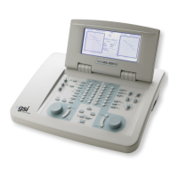
61 CLINICAL AUDIOMETER
Do not use a patch cord with the Talkback microphone as interference can
occur.
c. Use the supplied patch cords to connect the GSI 61 output jacks for all transducers
to the corresponding points in the connector panel on the outside of the examination
(sound) room. Refer to the Figures on page 2-23 for the optional High Frequency
installation. Plug the monitor headset into the rear panel jack.
Be certain that the transducers connect to the corresponding patch cords
through the connector panel.
d. Connect the optional speaker cable to the connector marked Speaker on the rear
of the GSI 61. Pass the other ends of the cable through the grommet holes in the
control panel of the sound room. Connect the cable marked “left” to the left
speaker, and the one marked “right” to the right speaker.
CAUTION: The wire ends must not touch each other or any other
conductive surface! Do not use patch cords with or instead of
the supplied speaker cables. Damage to amplifiers inside the
GSI 61 will occur.
e. Mount the speakers in the corners of the sound room. Position the speakers
three feet (one meter) from the patient. The cone of the speaker should be at
the same height as the ear of the average patient seated in the normal listening
position.
Note: All transducers are pre-calibrated except for the speakers.
Contact a local GSI representative to install and calibrate the sound field
system.
f. Plug the power cord into a grounded outlet.
g. Turn the unit on and observe that the GSI 61 is receiving power. (The small
power LED on the front panel is illuminated). The unit is initialized to Tone, Phone,
Right, 0 dB HL, 1000 Hz Channel 1; and Narrow Band Noise, Phone, Left
-10 dB HL, Channel 2.
h. Test all of the input and output transducers to verify that the signals and
communication functions are operating properly.
2-28 1761-0100 Rev. B
 Loading...