EasyManua.ls Logo

GSK 983Ma-H User Manual

Default Icon
32 pages
To Next Page IconTo Next Page
Page #1 background imageLoading...
Page #1 background image
Question and Answer IconNeed help?

Do you have a question about the GSK 983Ma-H and is the answer not in the manual?

GSK 983Ma-H Specifications

General IconGeneral
Program StorageFlash memory
Axis Control3
Spindle Override50-120%
Minimum Input Unit0.001mm
Rapid Traverse Override25%, 50%, 100%
Communication InterfaceUSB
Power SupplyAC 220V 50/60Hz
Operating Temperature0~45℃
Storage Temperature-20°C to 60°C

Summary

Preface and Safety Information

Critical Operational Warnings

Key safety warnings highlighting potential accidents from improper connection and operation.

Manufacturer and User Safety Duties

Defines responsibilities of both the manufacturer and the user regarding system safety.

System Precautions and Guidelines

NC Unit Interface Details

NC Unit Front Panel Connections

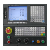
Illustrates the front panel of the NC unit, showing interfaces like USB and communication ports.

NC Unit Back Panel Connections

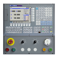
Depicts the rear panel of the NC unit, detailing various connection ports and basic circuits.

System Interconnect Diagram

Overall System Connectivity

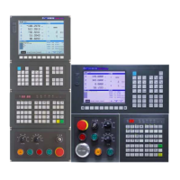
Provides a comprehensive block diagram illustrating the interconnection of all system components.

NC Unit to DA98D Drive Unit (No Brake) Connection

DA98D Drive Unit Wiring (No Brake)

Details the wiring connections between the NC Unit and the DA98D Drive Unit for systems without a brake.

NC Unit to DA98D Drive Unit (Z Axis Brake) Connection

DA98D Drive Unit Wiring (Z Axis Brake)

Details wiring connections between the NC Unit and DA98D Drive Unit for Z-axis with brake functionality.

NC Unit to Spindle Servo Drive Unit Connection

Spindle Servo Drive Unit Wiring

Illustrates the connection between the NC Unit and the Spindle Servo Drive Unit, including I/O unit mapping.

NC Unit to Spindle Inverter Connection

Spindle Inverter Wiring Details

Explains the connection between the NC Unit and the Spindle Inverter, including spindle encoder and notes.

NC Unit to I/O Unit Connection

External I/O Unit Connection

Details the serial connection (RS422) between the NC Unit and the External I/O Unit.

Machine Tool Panel Interfaces Overview

NC Unit to Operation Panel Connection

External MPG to Operation Panel Connection

NC Unit to PC Serial Connection

Z Axis Brake and System Power-on Control

External I/O Unit (X1) Interfaces

I/O Unit (X1) Signal Connectivity

I/O Points Definition (X1) - Input Signals (Part 1)

I/O Points Definition (X1) - Input Signals (Part 2)

I/O Points Definition (X1) - Output Signals

Spindle Orientation Detection Switch Installation

Z Axis 2nd Reference Point Detection Switch Installation

Related product manuals