Do you have a question about the GTO FM143 and is the answer not in the manual?
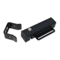
Lists all components provided with the Automatic Gate Lock for installation.
Details the mounting hardware required for various gate types and installation scenarios.
Step-by-step guide for installing the automatic gate lock on a single gate system.
Instructions for installing the automatic gate lock on dual gate systems, including sequencing.
Connects the gate lock to specific MM and TS operator models, detailing required jumpers.
Details wiring the gate lock for MM560, MM562, and Linear Pro 3000/4000XLS operator series.
Provides wiring instructions for MM272, HD272, MM262, MM362, MM462, and Linear Pro 2000XLS series.
Connects the gate lock to MM271 and MM260 operator models, including dip switch settings.
Details wiring the gate lock for MM360 operator models, noting dip switch setting for LOCK (OFF).
The GTO Automatic Gate Lock is a security device designed to enhance the safety and security of automatic gate systems. It works in conjunction with gate openers to provide a firm and secure closure, preventing the gate from being forced open. The lock is suitable for both single and dual gate installations, offering flexibility for various gate configurations.
The Automatic Gate Lock operates by engaging a lock catch against a lock receiver when the gate is in the closed position. This mechanical engagement ensures that the gate remains securely shut, even against external forces. The lock is designed to work with automatic gate openers, and its proper function relies on the gate closing firmly against a positive stop. The system includes a lock control board (Lock PCB) that manages the electronic release mechanism. In the event of an electronic malfunction or power outage, the lock is equipped with a manual release feature, allowing users to open the lock using a key. This ensures access even when the electronic system is disabled.