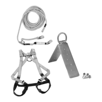
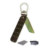
Connection Point
Adjusts to fit
roof pitch
Fastener Installation Hole
(x16 per side)
Components and Specifications
Materials: zinc-plated steel.
Guardian Fall Protection 6305 S. 231st St., Kent, WA 98032 phone: (800) 466-6385 fax: (800) 670-7892 www.guardianfall.com
3
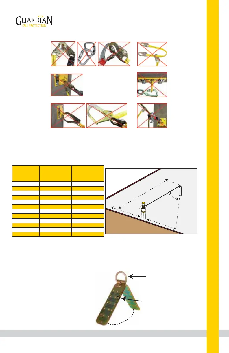
Correct Anchorage Positioning:
This chart details allowable working zones required
to reduce risk of swing falls and improper side loading.
ALWAYS adhere to information specified by chart.
Anchor Distance
From
Leading Edge (Y)
Working Distance
Along Roof Edge
(Either Direction) (X)
Working Angle
From
Perpendicular (Ø)
6’
10’
15’
20’
25’
30’
35’
40’
45’
50’
55’
60’
8’
9’ - 9”
11’ - 7”
13’ - 3”
14’ - 6”
16’
17’ - 2”
18’ - 3”
19’ - 4”
19’ - 10”
21’ - 4”
22’ - 3”
53°
45°
38°
33°
30°
28°
26°
24°
23°
21°
21°
21°
For example, if the anchorage connector is 6’ from the leading
edge (Y), the working distance (X) is 8’ in each direction from
the perpendicular, which translates to a 53° working angle.
Ø: Total Working Angle
X: Working Distance
Along Leading Edge
Y: Distance From
Leading Edge
X
Y
ø
X
Leading Edge
Two or more
snap hooks or
carabiners
connected to
each other. NO.
Two connectors
to same
D-ring. NO.
Connector
directly to
horizontal
lifeline. NO.
Connector
directly to
webbing.
NO.
Application
that places
load on gate.
NO.
Incompatible
or irregular
application,
which may
increase risk
of roll-out. NO.
 Loading...