SUGGESTED
WIRING
DIAGRAM
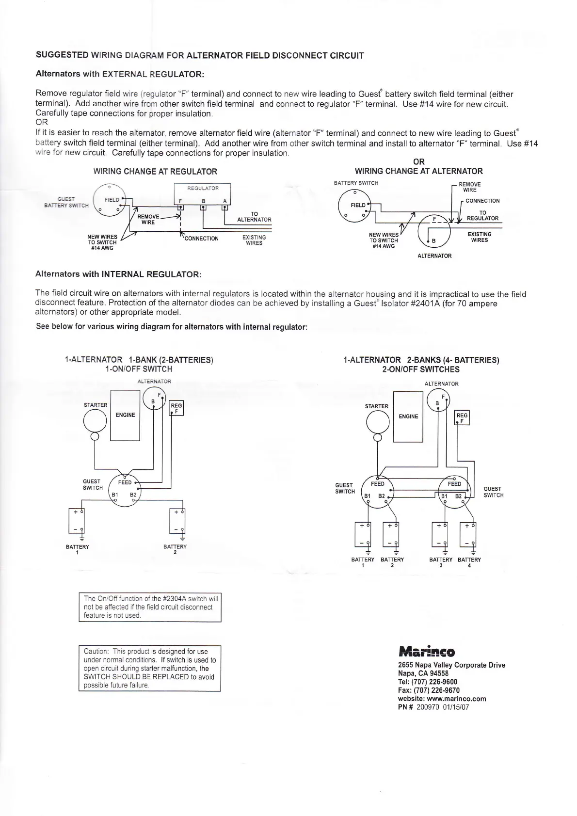
FOR ALTERNATOR FIELD DISCONNECT
CIRCUIT
Alternators
with
EXTERNAL
REGULATOR:
Remove
regulator
field
wire
(regulator
"F"
terminal) and connect to new wire leading
to Guest'battery switch field terminal
(either
terminal).
Add
another
wire
from other switch field terminal and connect to regulator
"F"
terminal. Use #14 wire for new
circuit.
Carefully
tape
connections
for
proper
insulation.
OR
lf it is
easier
to reach
the
alternator, remove
alternator
field wire
(alternator
"F"
terminal) and connect to new wire leading
to Guest'
battery
switch
field
terminal
(either
terminal). Add another wire from
other
switch
terminal and install to alternator
"F"
terminal. Use #14
''vire
for
new
circuit.
Carefully
tape connections
for
proper
insulation.
OR
WIRING
CHANGE
AT REGULATOR
WIRING CHANGE AT ALTERNATOR
GUEST
BATTERY
S1$TCH
Alternators
with INTERNAL
REGULATOR:
The field
circuit
wire on
alternators with iniernal regulators
is located
within the
alternator housing and it is impractical
to use the field
disconnectfeature.
Protectlon
of the alternatordiodes
can
be achieved by installing
a Guest'lsolator #2401A(for70
ampere
alternators)
or
other appropriate
model.
See
below for various
wiring diagram
for alternators with
internal regulator:
l.ALTERNATOR
1
-BANK
(2.BATTERIES)
1.ON/OFF
SWITCH
AITERNATOR
The
OniOff
function of the
#23044 switch will
not be affected if the fleld circuit
disconnect
feature is not used.
Caution: This
product
is designed for
use
under normal condrtions. lf
switch is used to
open circuit during starter malfunction, the
SWITCH SHOULD BE REPLACED
to avoid
possible
future failure.
1
-ALTERNATOR
2.BANKS
(4-
BATTERTES)
2-ON/OFF
SWITCHES
ALTERNATOR
GUEST
SWTCH
GUEST
SWITCH
BATTERY
1
BATTERY
2
BATTERY BATTERY
34
Marinco
2655 Napa Valley
Corporate Drive
Napa,
CA 94558
Tel:
(707)
226-9600
Fax:
(707)
226-9670
website: www.marinco.com
PN # 200970 01t15107
STARTER
E
F
I
/r.Er\
Bl s2>
vq/
t /
rieo
B1 82
I
\?3,
l"l
:"1
t. ll
 Loading...