AMPS AMPS
MODEL MOMENTARY CONTINUOUS
2110A 345 230
2111A 345 230
2112A 345
230
EASY INSTALLATION
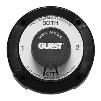
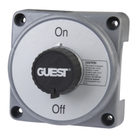
BATTERY SELECTOR SWITCHES #2110A, #2111A, AND ON-OFF SWITCH #2112A
Guest selector switches are
“
make-before-break
”
single-pole, triple-throw switches that permit the selection between either of two batteries
or banks of batteries, operation of both batteries or banks of batteries in parallel, or complete disconnect of both batteries or banks of batteries.
The switches are rated for 6,12, 24, or 32 volts:
Model 2110A switch features an alternator field disconnect which interrupts the alternator field when the switch is turned to the
“
off
”
position, thus
preventing electrical surges in the armature circuit which might burn out the alternator diodes or ancillary equipment. Models 2111A and 2112A
do not include this feature and should never be turned to the
“
off
”
position with engine running.
NOTE: These switches are designed as disconnect switches and are not to be used as load-breaking devices. If switch is used as load-breaking
device in emergency situation (e.g., starter malfunction), the switch should be replaced to avoid possible future failure.
MOUNTING: Switch should be located as close to (within 40
”
) the batteries as possible. The battery and starter cable should be as short as
possible. Mount on a flat surface in an area that will remain dry and is protected from abuse. OPTIONAL: It may be necessary to remove the
adapter ring on some boats where the battery switch is fed through a thick panelboard.
WIRING: The battery cable should be sized in accordance with the engine manufacturer’s recommendations. Other guides to wire sizes and
terminals may be obtained from the American Boat and Yacht Council electrical standards. The brass terminal studs for model 2110A, 2111A,
and 2112A are 3/8
”
diameter. Be sure all connections are securely tightened. Align the terminals such that they do not cause undue twisting at
the switch studs. See wiring diagram below for correct terminal installation. After connecting and mounting of switch, fasten the cables in
position with a suitable cable clamp no more than 6
”
from the switch. Clamp the remainder of the cable no more than 18
”
apart.
Note: If the switch is mounted in such a way that the terminals are exposed, then the terminals should be taped or covered in order to comply
with Federal Ignition Protection Codes.
OPERATION: Always reserve one battery for engine starting. Use the second battery for lights, appliances, and other ship’s service.
“
Both
”
position parallels batteries for emergency use.
CHARGING: Switch setting indicates battery(ies) being charged when engine is running.
SUGGESTED WIRING DIAGRAM FOR ALTERNATOR FIELD DISCONNECT CIRCUIT
Alternators with EXTERNAL REGULATOR:
Remove regulator field wire (regulator
“
F
”
terminal) and connect to new wire leading to Guest battery switch field terminal (either terminal). Add
another wire from other switch field terminal and connect to regulator
“
F
”
terminal. Use #14 AWG wire for new circuit. Carefully tape
connections for proper insulation.
OR
If it is easier to reach the alternator, remove alternator field wire (alternator
“
F
”
terminal) and connect to new wire leading to Guest battery switch
field terminal (either terminal). Add another wire from other switch terminal and install to alternator
“
F
”
terminal. Use #14 AWG wire for new circuit.
Carefully tape connections for proper insulation. Note:
The function of #2110A selector switch will not be affected if the field circuit disconnect
feature is not used.
Universal Mount
Battery Switch
®
®
R
NOTE: To maintain listed ratings use 2/0 cable
®
CABLE LUG INSTALLATION
WRONG RIGHT
Remove Top Nut Only
Removing Bottom Nut Will Damage The Switch
Tighten nut to 70 in-lbs.
REMOVABLE
ADAPTER RING
2
R
F
U
L
L
Y
E
N
G
A
G
E
D
A
T
D
E
T
E
N
T
S
1
OFF
BOTH
M
A
D
E
I
N
U.
S.
A
.