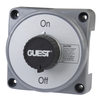
GIESr'
MODEL
#2304A
EXTRA.H EAVY-D
UTY ON/O FF
Battery
Switch
EASY INSTALLATION
Guest' Extra-Heavy Duty On/Off Switch is a single
pole,
singlethrow switch with
alternator field circuit disconnect for use where
high
amperage is required,
such as diesel engine starting. Raied
at 600
amps
continuous,
'1000
amps momentary, the switch is5112"
square and 3 1/2" high.
Warning: lt is important
that cold start amperage requirements
of
your
engine
do
not
exceed the rated
capacity
of this switch.
The switch features:
1 . Alternator field disconnect, which interrupts the
alternator-field
when
switch is
turned
1o 'loff'
position,
thus
preventing
electric
surges in the armature circuit
which
might burn out the alternator diodes.
Positive click stop in all
positions,
with large easyto-read
dial.
Rugged
polycarbonate
case with built-in
skirt to
protect
electrical connections.
Can be
panel
or
flush mounted.
Heavy-duty copper contacts.
For use with 6, 12, 24, and 32 volt
systems.
lnstallation
lnstructions
Mounting
Switch should be located as close to
the batteries as
possible
with regards
to convenience of operation. The battery and starter
cable
should be as short as
possible.
There are three mounting
positions:
1.
Surface
mounting with the
wires
going
through the
openings
at
the base of the switch.
2. Surface mounted with
a
hole in
the mounting surface to
permit
wires
to come through at the back of the switch.
3. Recessed mounting of the
switch through a hole in the
mounting
surface.
For surface
mounting,
place
the switch in the desired location and, using
the switch as a template, locate the four mounting
holes. Then
drill four equally-spaced #12 holes on 4
3/8" centers.
For
Lecessed
mount[g,
pla_ce
the
switch in the desired locatiQn,_and
using the switch as_a
templatg,_lo.cate
lhq
c54!q1 Cut_a
hole
5
1/4"
dia. to
permit
the silver face
plate
to extend throrigh
ihe mounting
surface. Then
put
the switcn fhrough t6e noie
from
thebackandlocateanddrill thefour#l2mountingholes.
Theseholesshouldbeon43/8"centers. lfflushmountingisdesired,
washers may be
used on the
mounting
bolts between the switch
flange
and the mounting surface to adjust the
portion
of the
switch
that comes through the
hole.
Wiring
1. The battery switch is designed to accept up to 4/0
cable.
The battery
cable should
be
sized
in accordance with the engine
manufaciurer's
recommendations. Other
guides
to wire sizes may be obtained from The
American
Boat and Yacht Council's
Electrical
StandardsEll.
Terminal
lugsshouldbesizedtoaccommodatethesizeofthewireandtheterminal bolts.
The
brass terminal bolts of
the
battery switch are %" in diameter
2. Wire for
alternator
field circuit disconnect
switch should be
#14 with terminal lugs on the ends.
(See
wiring diagrams
for
suggested
installations).
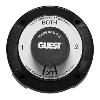
Recommended Mounting of Cables at Switch
Connect
cable
(A)
fronr
positive
post
of battery #1
to switch
terminal
#1 .
Connect
cable
(B)
from
positive post
of batlery
#2
to switch terminal #2.
Connect
cable
(C)
from
starter
solenoid and cable
(D)
from accessory
(load)
to Feeder terminal on
switch.
See "Wiring" for cable and terminal requirements.
CABLE
LUG
INSTALLATION
2.
3.
4.
E
1.
2.
.'t
4.
tutu
WRONG
Remove
Top Nut and Washer Only
Removing
Bottom Nut Will
Damage The
Switch
Tighten
nut to 150 inlbs,
RIGHT