Do you have a question about the GUIDANCE MARINE RadaScan and is the answer not in the manual?
Provides a general welcome and overview of the installer's guide content.
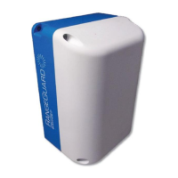
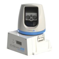
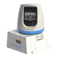
Details the RadaScan system's components: Sensor, Dashboard Software, and Responder.
Covers crucial safety precautions for installation and operation.
Details safety measures for non-ionising radiation emitted by the sensor.
Describes precautions to prevent electric shock during installation.
Explains procedures for safely disconnecting and isolating sensor equipment.
Provides instructions and safety advice for safely lifting the sensor unit.
Explains the identification and use of serial and software version numbers.
Provides guidelines and considerations for physically mounting the RadaScan sensor.
General recommendations for sensor placement on any vessel type.
Details requirements for plinths and brackets used for sensor mounting.
Explains how to configure sensor orientation parameters in the software.
Advises on preventing interference from other radar systems.
Describes sensor mounting for stern-facing operating areas.
Describes sensor mounting for forward-facing operating areas.
Describes sensor mounting for port/starboard facing operating areas.
Provides physical dimensions and mounting hole specifications for the sensor.
Offers a template for ensuring correct sensor mounting hole placement.
Details the direct connection method for sensor cabling.
Outlines the direct connection for low-temperature sensor variants.
Explains sensor connections using a 3-gland Ethernet box.
Explains sensor connections using a 4-gland Ethernet box.
Illustrates cable routing for direct sensor connections.
Illustrates cable routing for connections via a separate box.
Shows cable routing for different processor and monitor setups.
Describes the sensor's status and network information display.
Guides the user through the process of installing sensor software.
Provides physical dimensions for the Type 2 Marine Processor unit.
Details the connection ports and methods for the Type 2 Marine Processor.
Step-by-step guide for installing dashboard software on the processor.
Instructions for installing dashboard software on a Hatteland Panel PC.
Explains how to modify the sensor's IP address settings.
Covers procedures for starting and stopping the RadaScan Dashboard.
Guides on setting the system's date and time parameters.
Explains how to operate the on-screen keyboard for input.
Details how to access service mode for advanced settings.
Describes various configuration settings accessible via menu panes.
Configures DP message formats and data feed behaviour for system integration.
Explains how to adjust display modes and brightness.
Defines vessel dimensions and orientation for accurate tracking.
Specifies distances from the sensor to the vessel's bow and starboard side.
Defines the sensor's angular orientation relative to the vessel's centerline.
Configures a zone to mask unwanted radar returns from the vessel's structure.
Introduces the different models and types of RadaScan Responders.
Details optimal placement guidelines for responders to ensure signal quality.
Explains the methods and brackets for mounting responders.
Outlines the procedure for charging rechargeable responders.
Describes how to operate and check the status of responders.
Lists compliance with relevant international standards and directives.
Provides a list of part numbers for system components and accessories.
Details the various DP message formats supported by the system.
Specifies requirements for UPS and necessary cabling for the system.
Offers guidance for troubleshooting Ethernet connectivity issues.
Provides a checklist for verifying correct installation and configuration.
| Brand | GUIDANCE MARINE |
|---|---|
| Model | RadaScan |
| Category | Marine Equipment |
| Language | English |