Section 7
7-12
7.2.3.4. 6675A CPU and Display Power Supply PCB Test Procedure
1. Using a DMM, measure the DC voltages at the 6675A CPU and Display
Power Supply PCB test points. The voltages should be as shown in Table 7-
6.
2. Using an oscilloscope, measure the noise voltage levels at the 6675A CPU
and Display Power Supply PCB test points. The noise levels should be as
listed in Table 7-6.
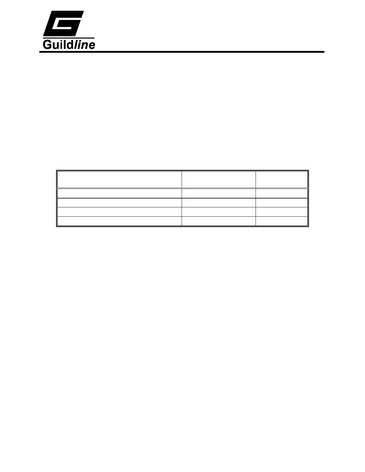
Test points on PCB Assy 19473 Voltage
(V)
Noise Limits
(mV p-p)
J3-1 with respect to J2-3 +5.0 ±5%
500
J3-3 with respect to J2-3 +10.0 ±10%
200
3-4 with respect to J2-3 -10.0 ±10%
200
J2-1 with respect to J2-3 +5.0 ±5%
500
Table 7-6 : Test Point Voltages Power Supply Assembly 19473
7.2.4. Alignment Procedure
7.2.4.1. Alignment Test Equipment Required
DMM (FLUKE 8840A or equiv.)
Oscilloscope (PHILIPS PM 3055 or equiv.)
Scopemeter (FLUKE 95 or equiv.)
Long-scale DMM (DATRON 1271 or equiv.)
Precision DC Voltage Standard (VALHALLA 2701C or equiv.)
Standard Resistor Set (GUILDLINE 9330 or equiv.)
Potentiometric Chart Recorder (ABB SE 120 or equiv.)
2 resistors @ 10 0.01% ¼W (General Radio or equivalent)
2 resistors @ 1 k 0.1% ¼W (Vishay S102K or equivalent)
2 resistors @ 100 k 0.1% ½W (Ultronix UL42 or equivalent)
 Loading...