Section 7
7-11
7.2.3.3. Nanovolt Dual Power Supply PCB Assy 19334 Test Procedure
1. Using a DMM, measure the DC voltages at the Nanovolt Dual Power
Supply PCB test points. The voltages should be as shown in Table 7-5.
NOTE : Ensure that a jumper is installed at E2.
2. Using an oscilloscope, measure the noise voltage levels at the Nanovolt
Dual Power Supply PCB test points. The noise levels should be as listed in
Table 7-5.
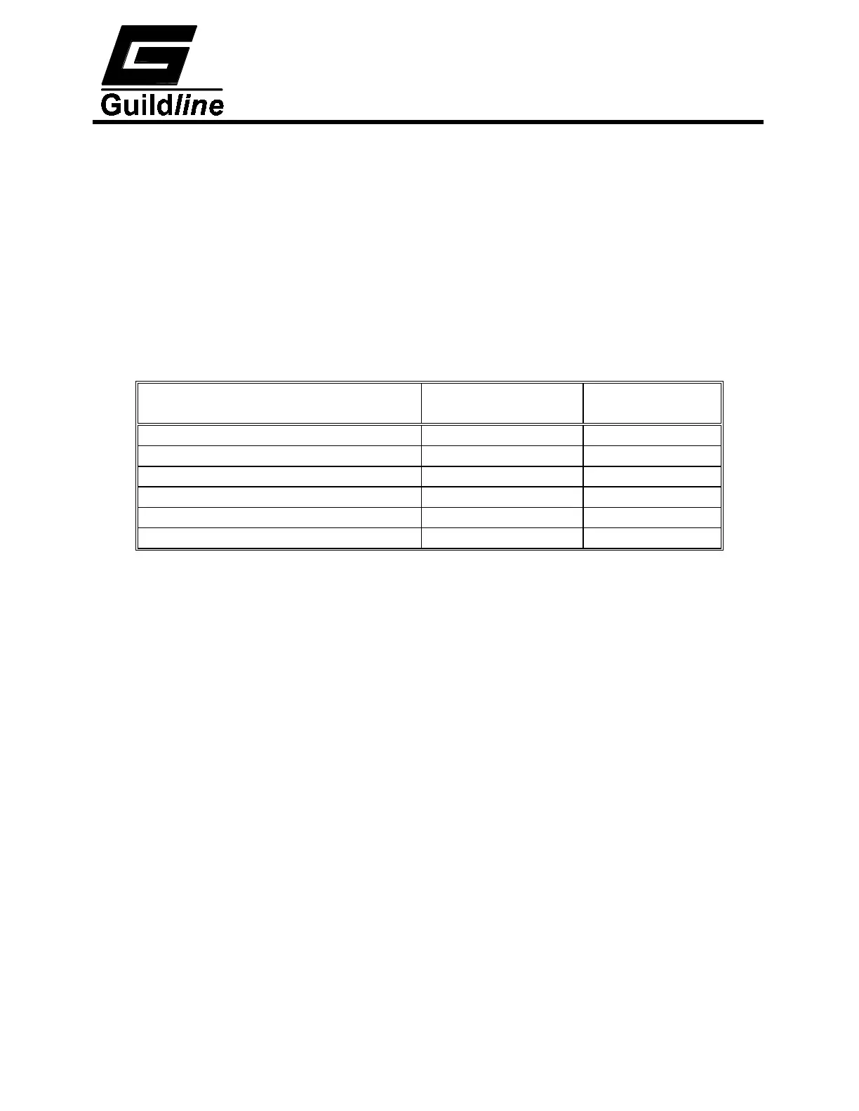
Test points on PCB Assy 19334 Voltage
(V)
Noise Limits
(mV p-p)
J3-2 with respect to GND1 +5.0 ±0.25 <500
J3-8 with respect to GND3 +5.0 ±0.25 <500
J6-3 with respect to GND3 +15.0 ±1.0 <100
J6-5 with respect to GND3 -15.0 ±1.0 <100
J6-6 with respect to GND3 -30.0 ±1.0 <100
J6-8 with respect to GND3 +30.0 ±1.0 <100
Table 7-5 : Test Point Voltages Assembly 19334
 Loading...