7
G503133 - R00
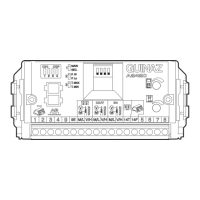
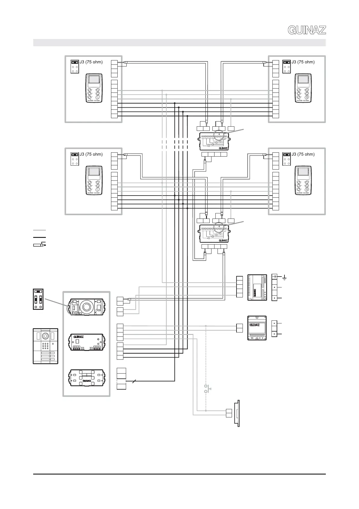
ESQUEMA DE CONEXIONES. CONNECTION DIAGRAM.
NOTA: Representada instalación manos libres con monitores blanco y negro, y cable coaxial para la señal de vídeo. Si para la transmisión
de la señal de vídeo se emplea cable de tipo par trenzado cat.5, Hay que cambiar los puentes de configuración en telecámara y bases
murales de monitores según se indica en la página 6.
NOTE: Representation of a hands-free installation with black and white monitors and coaxial cable for the video signal.
If a twisted pair cable type cat..5 Is used for transmitting the video signal, the configuration bridges in camera and the wall base of the
monitor will have to be changed, in accordance with that indicated in page 6.
V/H
M/L
M/L
12
13
11
5
10
M1934
V/H
5F
14
M/L
V/H
4
5
V/H
M/L
M/L
V/H
PUL
8
7
6
12
13
11
5
10
PUL
8
7
6
PUL 1
PUL n
220 V.
F1320
PRIM
F1318
220 V.
PRIM
11
5F
5F
14
2
11
G1810D
G1220
G02XX
Configuración para cable coaxial.
Configuration for coaxial cable.
CONEXIÓN MEDIANTE LATIGUILLOS: DESDE EL MÓDULO
TELECÁMARA AL MÓDULO CONTROL AUDIO, Y DESDE ÉSTE AL
MÓDULO PULSADORES.
CONNECTIONS BY MEANS OF CONNECTORS:
FROM CAMERA MODULE TO AUDIO CONTROL MODULE, AND OF
THIS TO PUSH-BUTTON MODULE.
1
2
3
6
7
8
1
PUL1
PUL2
PULn
n PUL
4
3
C02098
V/H
M/L
M/L
V/H
12
13
11
5
10
PUL
8
7
6
V/H
M/L
M/L
12
13
11
5
10
V/H
PUL
8
7
6
Cortar resistencia
Shut-off the resistance
Pulsador adicional abrepuertas
Additional door opener push-button
V MMV
M4
V4 M1 V1 10
V MMV
PUL 4
PUL n-4
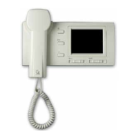
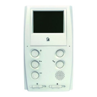
M2710D
MONITOR n-4
M2710D
MONITOR n
M2710D
MONITOR 1
M2710D
MONITOR 4
No cortar resistencia
Do no shut-off the resistance
M4
V4 M1 V1 10
V
MMVV MMV
M1934
CABLE ALIMENTACIÓN. POWER SUPPLY CABLE.
CABLE SEÑAL. SIGNAL CABLE.
CABLE COAXIAL 75 ohm. 75 Ohm COAXIAL CABLE.
 Loading...