3. Controls and Indications:
(See Figure 9 and Figure 10.)
NOTE:
A full description of the Flight Controls 2/3 and
Hydraulics 2/3 synoptic pages appears in section
2B-07-00.
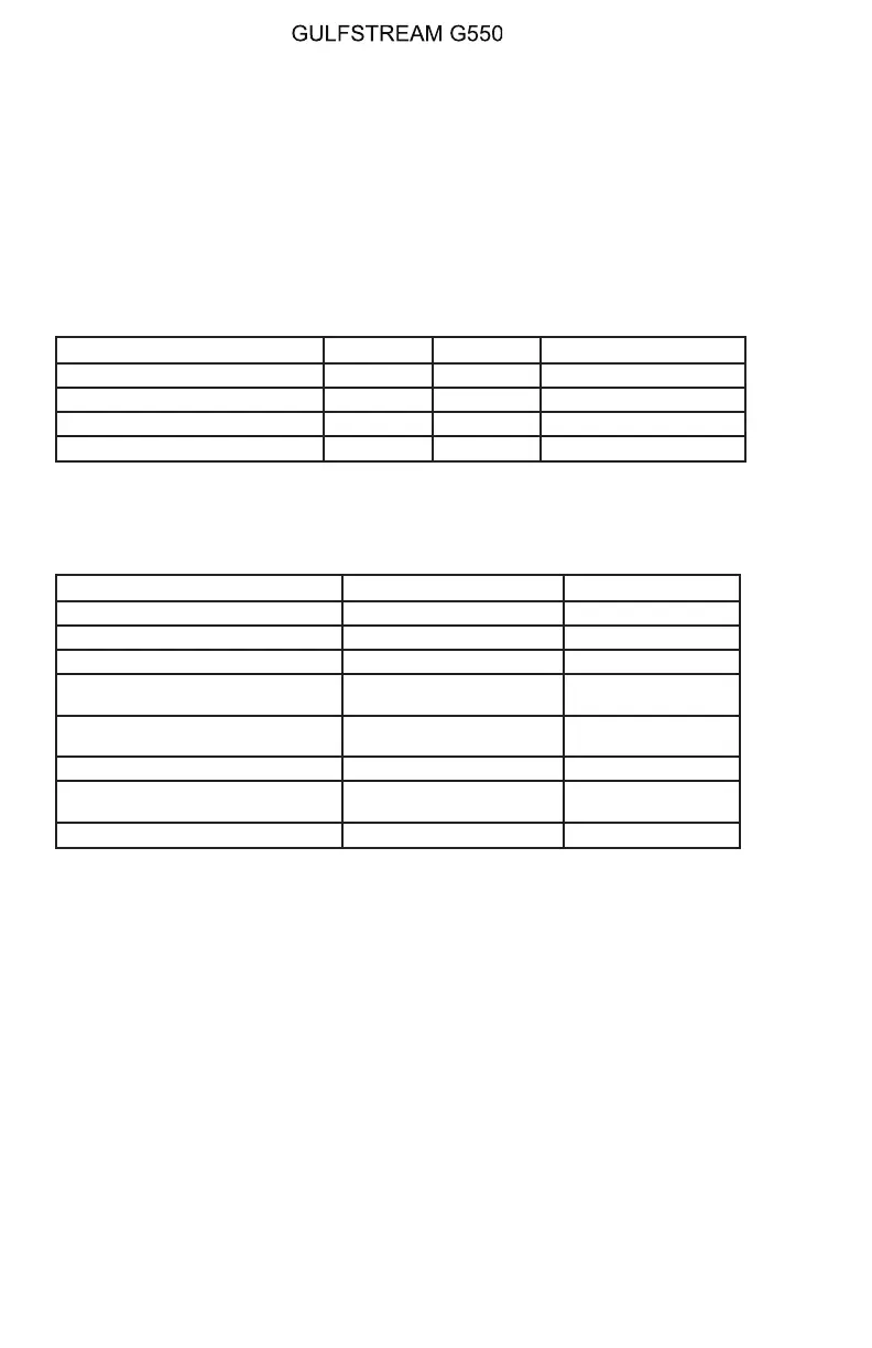
A. Circuit Breakers (CBs):
The following CBs protect the rudder flight controls:
Circuit Breaker Name: CB Panel: Location: Power Source:
RUDDER HYD S/O CPOP C-3 R ESS DC Bus
YAW DAMP SERVO #1 POP D-6 L ESS DC Bus
YAW DAMP SERVO #2 CPOP D-6 R ESS DC Bus
AUX HYD PUMP LEER C-16 L ESS DC Bus
B. Crew Alerting System (CAS) Messages:
The following CAS messages are associated with the yaw flight controls
system:
Area Monitored: CAS Message: Message Color:
Rudder Hydraulic Shutoff Valves Rudder Hydraulics Off Amber
Yaw Damper Servo Valves Yaw Damper 1-2 Fail Amber
YAW DAMP ENG/DISENG Switch Yaw Damper Off Amber
Autopilot, YAW DAMP ENG/
DISENG Switch
No YD Turn Coordination Blue
MWS Software, Aircraft Speed,
Rudder Position (RVDT)
Rudder Limit Blue
Rudder Hydraulic Shutoff Valves Single Rudder Blue
Standby Rudder Switch / AUX
Pump
Standby Rudder Hyd On Blue
Yaw Damper Servo Valves YD 1-2 Power Fail Blue
4. Limitations:
A. Yaw Damper Inoperative Speeds:
Maximum Speeds:
• Above 10,000 Feet: 260 KTS / 0.80 MT
• Below 10,000 Feet: 250 KCAS
Minimum Speeds:
• Above 20,000 Feet: 210 KTS
• Below 20,000 Feet:
The minimum speed is in accordance with the following schedule
until ready to configure for approach and landing. V
REF, as shown on
the airspeed tape of the PFD, is the approach speed for landing for
the current flap setting.
OPERATING MANUAL
PRODUCTION AIRCRAFT SYSTEMS2A-27-00
Page 28
August 14/03
 Loading...