function of the SWPS is operational only with the aircraft on the ground to
preclude inadvertent activation of the system during flight.
4. Controls and Indications:
(See Figure 0.)
NOTE:
A full description of the Primary Flight Display appears
in section 2B-02-00: Electronic Display System
Description.
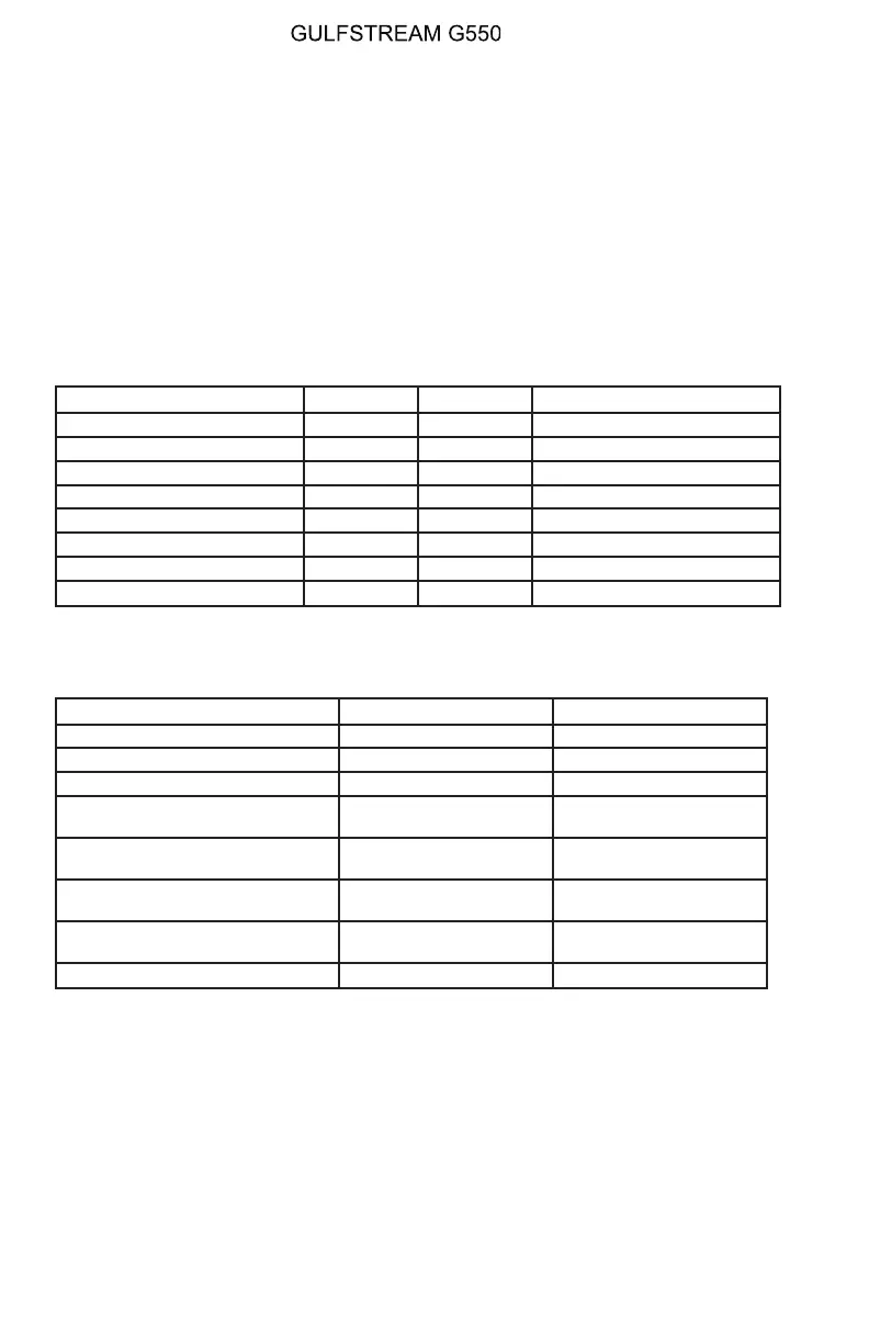
A. Circuit Breakers (CBs):
The following CBs provide power to SWPS components:
Circuit Breaker Name: CB Panel: Location: Power Source:
AOA PROBE #1 POWER LEER F-2 Left Essential DC Bus
#1 AOA HTR POP A-2 Left Essential DC Bus
AOA PROBE #2 POWER REER F-13 Right Essential DC Bus
#2 AOA HTR CPOP A-2 Right Essential DC Bus
SHAKER #1 POP E-6 Left Essential DC Bus
SHAKER #2 CPOP E-6 Right Main DC Bus
STALL BARR VALVE #1 POP E-5 Left Essential DC Bus
STALL BARR VALVE #2 CPOP E-5 Right Essential DC Bus
B. Crew Alerting System (CAS) Messages:
The following CAS messages are associated with the SWPS system:
Area Monitored: CAS Message: Message Color:
AOA Probe AOA Probe 1-2 Fail Amber
SWPS function AOA Miscompare Amber
SWPS function Stall Barrier 1-2 Amber
SWPS function / STALL BARR
Switch
Stall Barrier Off Amber
SWPS function / hydraulic
actuator
Stick Push 1-2 Fault Amber
SWPS function / hydraulic
actuator
Stick Push 1-2 Fail Amber
SWPS function / hydraulic
actuators
Stick Push Unavailable Amber
SWPS function / electric motor Stick Shake 1-2 Fail Blue
5. Limitations:
A. AFM Limitations for Stall Warning / Stall Barrier System (FAA Certified
Airplanes):
(1) Takeoff Requirements:
Both stall warning / stall barrier systems must be operable for
takeoff.
(2) Use of System:
Operative stall barrier systems must be ON during all flight
OPERATING MANUAL
PRODUCTION AIRCRAFT SYSTEMS2A-27-00
Page 64
August 14/03
 Loading...