system can be activated. Selection of the STBY RUD switch, located on
the lower portion of the pilot’s flight panel, to ON activates the AUX pump.
AUX pressure opens a pilot-pressure operated valve to provide pressure to
the rudder actuator and a message is displayed on CAS. System operation
can be viewed on the HYDRAULICS synoptic page. Rudder operation will
be normal from the flight crew’s perspective until nose landing gear weight-
on-wheels is achieved, at which point AUX pressure is removed from the
actuator. The Yaw Damper system continues to function normally while the
Standby Rudder system is in operation.
E. Yaw Damper System:
(See Figure 7.)
A yaw damping channel is integrated within each of the two Flight
Guidance Computers (FGCs). Inputs received by the active FGC is cross-
checked and valid commands are transmitted to the rudder dual trim servo
for output to the rudder actuator. Detected faults prompt messages for
display on CAS. The yaw damper system is fail-operational in that should
one yaw damping channel (or FGC) fail, the remaining FGC can support
full system operation.
Both yaw damper channels are controlled using the YAW DAMP ENG/
DISENG switch, located on the lower portion of the pilot’s flight panel.
Power to the Yaw Damper system is provided by the Left Essential DC Bus
(YD 1) and Right Essential DC Bus (YD 2). When the ENG/DISENG switch
is selected to DISENG, the system is disengaged and a message is
displayed on CAS.
F. Rudder Trim System:
(See Figure 8.)
The Rudder Trim system allows fine position adjustment of the rudder to a
desired position. This is accomplished through a trim adjustment knob,
located on the cockpit center pedestal, to a maximum indicated 7.5
degrees left or right. There is no rudder trim tab on the rudder control
surface; mechanical trim inputs to the rudder actuator offset the entire
surface.
3. Controls and Indications:
(See Figure 7 and Figure 8.)
NOTE:
A full description of the FLIGHT CONTROLS and
HYDRAULICS synoptic pages can be found in section
2B-03-00: Engine Instruments and Crew Alerting
System Description.
A. Circuit Breakers (CBs):
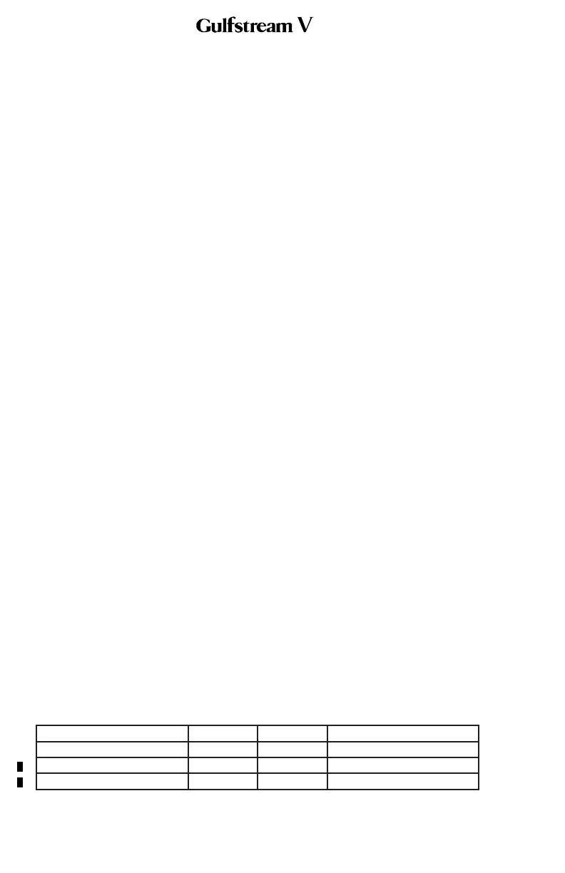
The yaw flight controls system is protected by the following CBs:
Circuit Breaker Name: CB Panel: Location: Power Source:
RUDDER HYD S/O CPOP C-3 R ESS DC Bus
IAC #1 POP D-8 L ESS DC Bus
IAC #2 CPOP D-8 R ESS DC Bus
OPERATING MANUAL
PRODUCTION AIRCRAFT SYSTEMS2A-27-00
Page 18
May 22/01
 Loading...