This is accomplished through the use of the electric pitch trim switch
located on each control wheel. While in the EMER STAB mode, a message
is displayed on CAS.
3. Controls and Indications:
(See Figure 10 and Figure 11.)
NOTE:
A full description of the Primary Flight Display can be
found in section 2B-02-00: Electronic Display System
Description. A full description of the FLIGHT
CONTROLS synoptic page can be found in section
2B-03-00: Engine Instruments and Crew Alerting
System Description.
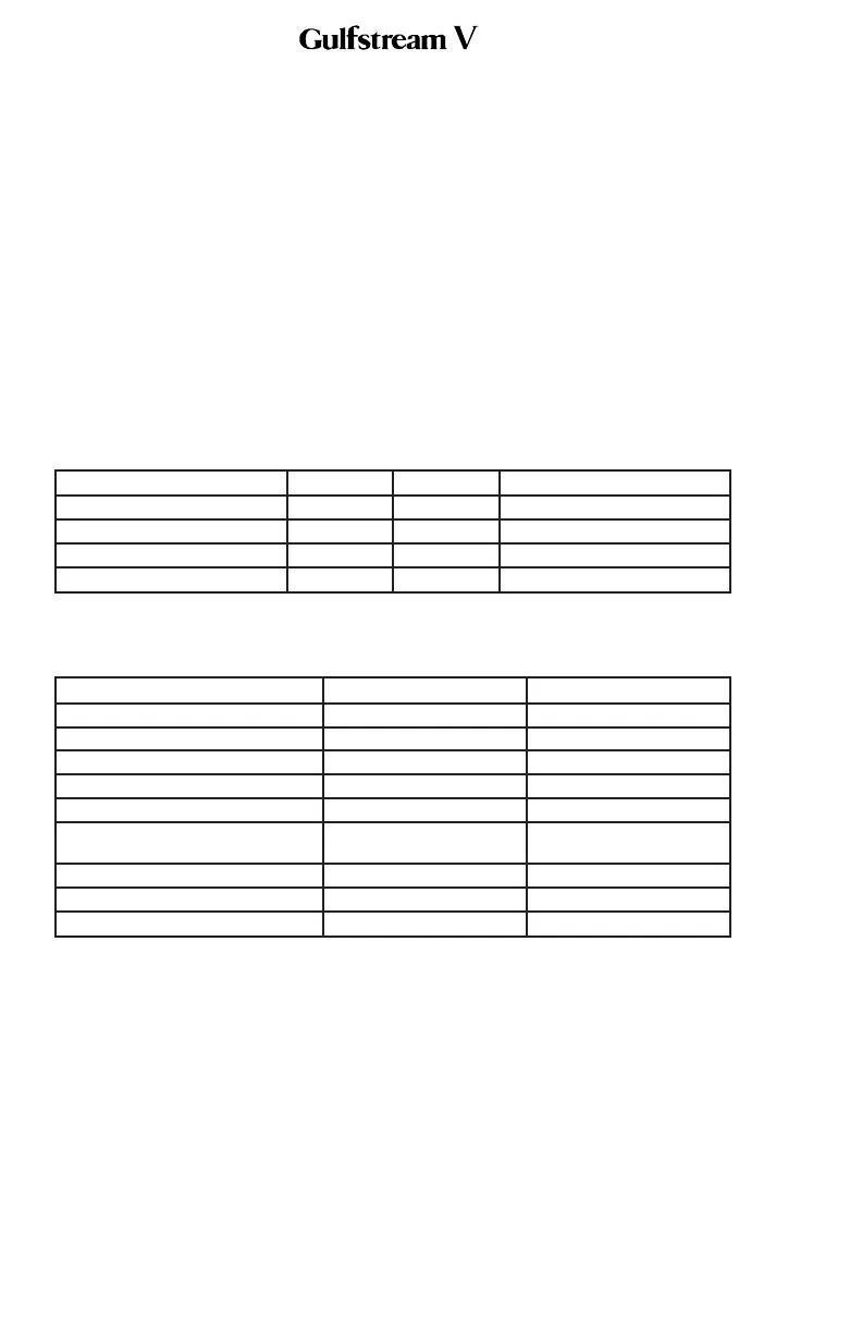
A. Circuit Breakers (CBs):
The horizontal stabilizer system is protected by the following CBs:
Circuit Breaker Name: CB Panel: Location: Power Source:
FLAP/STAB LEFT DC POP C-6 L ESS DC Bus
FLAP/STAB RIGHT DC CPOP C-6 R ESS DC Bus
FLAP/STAB L STBY AC POP D-2 L STBY AC Bus
FLAP/STAB R STBY AC CPOP D-2 R STBY AC Bus
B. Crew Alerting System (CAS) Messages:
CAS messages associated with the horizontal stabilizer system are:
Area Monitored: CAS Message: Message Color:
FCU FLAP/STAB AUTORIG Amber
FCU EMERG STAB ON A-B Amber
FCU FLP/STB SYNC FAIL Amber
FCU STABILIZER FAILED Amber
FCU UNCMDED STAB Amber
FCU
FLP/STB
MISCOMPARE
Amber
FCU FLP/STB MX RQD A-B Blue
FCU FLP/STB SYS FL A-B Blue
FCU STAB SYNCING A-B Blue
4. Limitations:
There are no limitations established for the horizontal stabilizer system at the time
of this revision.
OPERATING MANUAL
PRODUCTION AIRCRAFT SYSTEMS2A-27-00
Page 28
May 22/01
 Loading...