5
BC
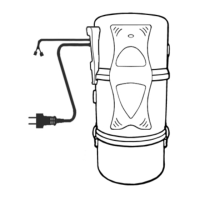
– Suporte de parede e parafusos; – Suportes da central;
DBLateralEF – Cabo de ligação à tubagem de aspiração;
G – Entrada de ar; H – Cabo de Alimentação;
I – LED de energia (quando aplicável); J – Saída de Ar;
K – Frente; L – Fechos do balde; M – Balde reservatório de lixo;
B
A - Wall support and srews; B - Unit support; 1 – Side panel;
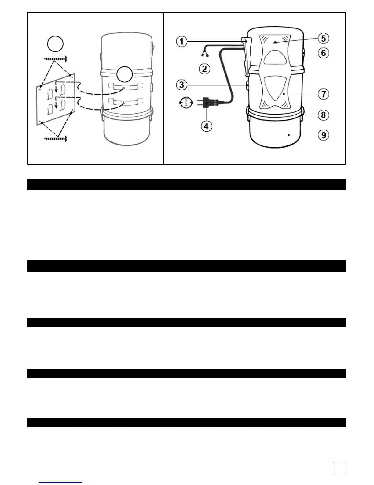
2 – Connection to the Central Vacuum system cable, 3 – Air entrance; 4 – Power cord;
5 – Power LED; 6 - Air Out; 7 – Front panel; 8 – Latches; 9 – Tank;
3NNN
A - Support mural et srews; B - Support de l'unité; 1 - Face latérale;
2 - Le raccordement au câble du système d'aspirateur central, 3 - entrée d'air; 4 - Le cordon d'alimentation;
5 - Power LED; 6 - Air Out; 7 - visage d'unité; 8 - supports de réservoir; 9 - Citerne;
C
A – Apoyo de pared y tornillos B – Apoyo de la central; 1 – Lateral; 2 – Conexion por cable a la linea de succion;
3 – Entrada de aire; 4 – Cable de Alimentacion; 5 – LED de energia (cuando aplicable); 6 – Salída de Aire;
7 – Frente; 8 – Sujetadores del cuba; 9 – Cuba de residuos;
A - Wandhalterung und Schrauben; B - Referat Unterstützung; 1 - Side Gesicht;
2 - Anschluss an das Central Vacuum-Kabel, 3 - Air Eingang; 4 - Netzkabel;
5 - Power-LED; 6 - Air Out; 7 - Einheit Gesicht; 8 - Tank Klammern; 9 - Tank;