This document describes the CO2 Monitor & Controller with Remote Sensor (Valve), model SA1600PRO, designed for monitoring and controlling CO2 levels in confined spaces.
Function Description
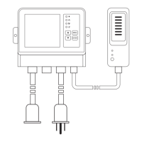
The device serves as a CO2 monitor and controller with a remote photocell sensor. It is designed to be a plug-and-play product, using AC power through a wall socket to control other connected equipment such as CO2 cylinder/generator/regulator or ventilation fans. It provides real-time display of CO2 concentration and allows for setting CO2 zone values and controlling output power supply. The controller unit features a large HD display and touch button operation.
Important Technical Specifications
- Model: SA1600PRO
- Measurement Range: 0-5000ppm (0-10000ppm optional)
- Accuracy:
- 0-3000ppm: ±50ppm +5%reading
- ≥3000ppm: ±50ppm +7%reading
- Warm-up Time: 30 seconds (cold start) @ 25°C
- Response Time: 63% step change < 2 min, or 90% step change < 4.6 min
- Operating Temperature: 32°F to 122°F (0°C to 50°C)
- Storage Temperature: 14°F to 140°F (-10°C to 60°C)
- Operating & Storage RH: 5-95% (non-condensing)
- Dimension:
- Control unit: 166 x 45.5 x 122 (mm)
- Sensor unit: 50 x 34.5 x 130 (mm)
- Weight: 1.50kgs (overall package)
- Power Input: AC100-240VAC
- Output Socket Load: 5A AC
- Sensor Type: 2-Channel Low Drift NDIR CO2 Sensor
- Sensor Cable Length: 5 meters, four-core shielded signal cable, waterproof aviation plug
- Power Input Cable: 1.5m
- Power Output Cable: 0.75m
Usage Features
The device is equipped with a built-in photocell sensor that automatically detects whether it is day or night. This feature allows the user to override the CO2 control and shut off the CO2 generator or regulator by turning off the output power during the night. If the photocell detects light and the CO2 level is low for more than 30 seconds, the device will start the CO2 generator by turning on output power. Users can choose to turn off this function, in which case the relay output power will only be controlled by the CO2 level, regardless of day or night.
The CO2 output control operates based on the set CO2 concentration. Output power is activated when the CO2 concentration is below "Set Center + (1/2) Set zone" and deactivated when CO2 concentration is over "Set Center - (1/2) Set zone". For example, if the Set Center is 1200ppm and the Set zone is 200ppm, the output power will shut off when CO2 is over 1200 + (1/2)*200 = 1300ppm, and power on when CO2 is below 1200 - (1/2)*200 = 1100ppm.
The controller panel features a power supply indicator (green light on), solenoid valve indicator (yellow light on), fan indicator (optional, not available on all products), and a light-sensitive indicator. Buttons include:
- Up arrow: Increase the value in selection mode or settings.
- Down arrow: Decrease the value in selection mode or settings.
- MENU: Enter settings.
- ENTER: Save and complete the settings.
The LCD display shows the date, time, CO2 reading, CO2 center value (default 1200ppm), CO2 zone value (default 200ppm), working time (default 0 second), and interval time (default 0 second). The menu bar includes icons for setup menu, calibration menu, time menu, valve control status, photosensitive mode on, and photosensitive mode off.
Operating Instructions:
- Installation: Plug the piggyback into the power socket. Connect the sensor to Port 1 and the valve/fan to Port 2. Ensure proper alignment to avoid breaking pins.
- Power On: Plug the power supply into the wall socket. The full screen will display after a 10-second countdown.
- Ready to Use: Once the countdown is complete, the product is ready. No additional setup or calibration is needed initially. Measured CO2 readings refresh every 6 seconds.
- Ambient CO2 Readings: The device will constantly display ambient CO2 readings, Set Center value, and Set Zone value on the screen. Avoid breathing directly on the remote sensor unit as it affects CO2 readings and accuracy.
- Backlit Display: Pressing any button will turn on the backlight, which lasts about 30 seconds.
Settings:
- Main Menu Functions: Press MENU to bring up the menu bar. Navigate using up/down arrows. Press MENU again to exit.
- Menu Function Settings: When a function icon is flashing, press ENTER to select it. Use up/down arrows to increase or decrease the value. Press ENTER one more time to confirm. If no button is pressed for 1 minute, the menu bar will shut off, and the device will revert to the normal state.
- CO2 Center Value, Zone Value, Working Time, and Interval Time Settings: Access these settings via the setup menu icon. Follow the on-screen prompts to adjust values using the up/down arrows and ENTER button.
- Date & Time Setting: Access these settings via the time menu icon. Press ENTER to set and save as a 24-hour system. Press ENTER while AM and PM flash simultaneously to save.
Maintenance Features
- Calibration Menu: CO2 400ppm one-key calibration.
- Re-calibration (Use with caution): To calibrate the device with outside atmospheric CO2 level 400ppm, press ENTER to bring up the menu bar, select the calibration icon, and press ENTER. Press ENTER for one more time to confirm. Then hold ENTER for 3 seconds until a beep is heard. After 250 seconds countdown, the CO2 Zone value will be displayed. Place the device outside for 20 minutes to complete the calibration.
- Notice: Keep the device away from CO2 sources, direct sunlight, and water during calibration. This device is well calibrated with standard 400ppm CO2 gas. Do not calibrate this device in unknown atmospheric CO2 levels, or it will be inaccurately calibrated into 400ppm.
- Restore Factory Setting: In normal state, hold ENTER for 3 seconds until a beep is heard to reset the device to factory settings. Once selected, the Set Center value is 1200ppm, Set Zone value is 200ppm, Set working time is 0 second, and Set interval time is 0 second.
Cautions:
- Keep the controller unit and sensor kit away from water mist, as it affects accuracy and product lifetime.
- Use the provided screws to install the controller unit and remote sensor kit firmly on the wall.
- Before powering on, ensure the controller and sensor kit are firmly installed on the wall.
- If the display shows E1, it means the remote sensor kit is not connected properly.
Disclaimers:
This device is not intended for workplace hazard CO2 monitoring, nor intended as a definitive monitor for human or animal health institutions, life sustenance, or any medical-related situation. The manufacturer assumes no responsibility for any damage or loss suffered by the user or any third party arising through the use of this product or its malfunction.