Connecting the Sensors
Complete the following steps to connect the control box to the required components:
1) Make sure the monitor is NOT connected to electricity.
2) Open the enclosure by releasing the two latches on the right side of the enclosure.
3) The sensor cables may already be connected to the terminal blodks. If they are not or more
sensors are being added, feed the cables through the most convenient strain relief bushing on
the bottom of the box, then connect the wires up to the proper terminal block.
➔ For Anderson digital sensors (1-4), match the ‘1’, ‘2’ and ‘3’ on the sensor cable to the
corresponding numbers on the terminal block.
1 – Signal Ground
2 – Signal Input
3 – + 5 VDC supply
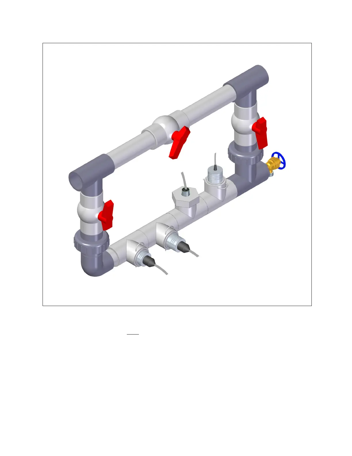
4
Sample valve
for taking water
samples.
Valve provides restriction to
main water line to force flow
through sensor manifold.
Adjust for moderate
flow through
the manifold.
Sensor Bypass Loop
Showing proper sensor positions
IMPORTANT: Be certain
both isolation valves are
open during normal
operation. Otherwise
the unit will not
operate properly.
Isolation
Valve
Anderson pH Electrode
(Mount Vertically)
Sample valve
for taking water
samples.
pH Electrode
cable connects to
Anderson signal
converter
Anderson pH Electrode
(Mount Vertically)
Anderson supplied
toroidal EC sensor
(Mount Vertically)
Isolation
Valve
Anderson digital
EC sensor
(Mount horizontally)
Anderson temperature
sensor (Mount horizontally)
Illustration 1
 Loading...