Do you have a question about the Hachette U-BOAT U 96 and is the answer not in the manual?
Steps for assembling the forward crew quarters, including bunks and dividers.
Steps to build the commander's quarters, adding a bunk, radio, lockers, and toilet.
Assembling furniture like stools and tables for the radio and listening rooms.
Constructing door frames and partitions for the radio and listening areas.
Installing the assembled door frame and partitions into the model.
Testing the functionality of the supplied LED cables with a test PCB.
Mounting the main PCB and connecting all LED cables and switches to the circuit board.
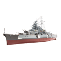
This manual describes the assembly of a model of the iconic World War II U-Boat, U 96. Specifically, it covers Pack 6, which includes Kits 21-24, focusing on the forward crew quarters, commander's quarters, radio room, listening room, and the forward Printed Circuit Board (PCB). The overall function of this device is to allow enthusiasts to construct a detailed, scaled replica of the U 96 submarine, providing an immersive and educational building experience.
Kit 21 initiates the assembly of the forward crew quarters, which are essential internal sections of the submarine model. These quarters are designed to house the crew and include bunks, lockers, and room dividers, replicating the cramped yet functional living spaces within a real U-Boat. The primary function of this kit is to build the structural and furnishing elements of these living areas, laying the groundwork for further interior detailing.
The assembly process for the forward crew quarters involves several distinct steps, starting with the preparation of bunk frames and individual bunks. Users will first separate three bunks from their frame and apply glue to the pegs on their undersides before attaching them to the bunk frames. These bunk frames are then secured to the forward bunk room deck. Room dividers are introduced next, with lockers being attached to them. The manual guides users to apply glue to specific raised sockets within the lockers and on the room dividers to ensure a secure fit. The toilet bulkhead is also integrated into the room divider assembly. Bunk rails are then detached from their frame and carefully glued into recesses on the room dividers, connecting different sections of the living space. Finally, bunk spacers are fitted between room dividers, and the remaining bunks are installed, completing the initial forward bunk room assembly with bunkers and lockers. The process emphasizes careful alignment and secure gluing to ensure the structural integrity and aesthetic accuracy of the model's interior.
While this kit primarily focuses on initial assembly, the careful application of glue and precise fitting of parts contribute to the long-term stability of the model. Ensuring all connections are firm during assembly minimizes the need for future repairs or re-attachments. The use of appropriate adhesives, as implied by the instructions, is crucial for the durability of the assembled components.
Kit 22 expands on the interior construction by adding the commander's quarters and further detailing the crew quarters. This kit introduces electronic components, such as a radio, and essential furnishings like a bedside table and lockers for the commander. It also includes a toilet door and additional bulkhead panelling for the crew quarters. The function is to enrich the internal environment of the model, adding specific areas and equipment that reflect the operational reality of a U-Boat.
Assembly begins by placing the previously constructed forward crew quarters assembly on a work surface. The commander's quarters are then furnished with a radio, lockers, and a bedside table. The lamp, initially part of a frame, is detached and prepared for installation. Glue is applied to the tabs on the back of the bedside table, which is then inserted into slots on the room divider. Lockers are attached to the room divider by applying glue to raised sockets. The radio is fitted into a recess at the top of the lockers, secured with glue on its pegs. A lamp is then glued into a slit on the outer edge of the room divider, to the left of the lockers. The circuit breaker door and a separate room divider are joined at right angles using glue at their contact points. This combined assembly is then attached to the bunk room deck. A fire extinguisher is added to the bottom of the circuit breaker door. The focus then shifts to the opposite end of the forward crew quarters, where a toilet roll holder is separated from its frame, glued, and fitted into a slot in the toilet bulkhead. Finally, bulkhead panelling is installed onto the room dividers, ensuring its slots fit securely onto the tabs. The toilet door is test-fitted and, if necessary, adjusted by removing a lower hinge before being glued into place, completing the commander's bunk and toilet area.
Similar to Kit 21, the emphasis on secure gluing and proper fitting during assembly is key to the longevity of these detailed interior sections. The instructions for test-fitting the toilet door suggest a practical approach to ensure parts fit correctly before final adhesion, which helps prevent damage or misalignment over time.
Kit 23 focuses on assembling and installing the furniture and bulkheads for the radio and listening rooms within the forward crew quarters. These rooms are critical operational areas of the submarine, and this kit aims to replicate their appearance and equipment. The function is to create these specialized compartments, complete with their unique furnishings and partitions, further enhancing the model's internal realism.
The assembly process for the radio and listening rooms begins with the construction of furniture. Stool seats and legs are detached from their frame, glued together at their pegs, and then fitted into recesses on the underside of the seats, creating two identical stools. These stools are then glued into corresponding holes on the bunk room deck. Next, tabletops and tables for both the radio and listening rooms are detached from their frames. Glue is applied to the pegs on the underside of the tabletops, which are then fitted onto their respective tables. These assembled tables are subsequently glued onto the bunk room deck.
The next stage involves the door frame and room partitions. The radio room door and listening room door are arranged, ensuring the raised rectangle is above the diamond shape. The door frame is placed on the work surface, and the radio room door is push-fitted into its left hinge, followed by the listening room door into its right hinge, ensuring both doors retain movement. Various equipment parts (E, M, A, B) are detached from their frames and glued onto the partition bulkheads (23-10 and 23-11) at indicated pegs and contact points. Part F is glued to room divider 23-10, and parts K and L are added to room divider 23-3. Part G is glued into the opening of part D, which is then inserted into the outer angled slot at the top of part L. Parts I and N are glued to the listening room bulkhead partition 23-11.
Finally, the partitions and doors are installed. The listening room partition (23-11) is aligned and glued to the door frame (23-12). Then, partition 23-10 is glued onto the door frame. The entire assembly, comprising the door frame and both partition bulkheads, is then attached to the deck of the forward crew quarters (21-1) by applying glue to the bottom edges and lower pegs. Part J is glued inside the opening of part H, which is then attached to the tabletop Q in the listening room. Part C is then glued to the peg of C and inserted into the slot in tabletop R in the radio room. The two bench tops (S) and legs (23-7) are removed from their frames, glued together, and then attached to the bunk room deck, completing the furnished radio and listening rooms.
The detailed instructions for assembling small furniture pieces and intricate partitions highlight the importance of careful handling and precise gluing. Ensuring that doors retain movement after fitting suggests a design consideration for interactive elements, which requires careful assembly to avoid stiffness or breakage. Regular dusting with a soft brush or cloth would be appropriate for maintaining the appearance of these detailed interior sections.
Kit 24 introduces the electrical components of the model, specifically the forward Printed Circuit Board (PCB) and associated LED cables. The primary function of this kit is to integrate the lighting system into the bow section of the U-Boat model. This involves testing the LEDs, mounting the PCB, and connecting various cables from the bow section and the LED cables to the circuit board, bringing the model's lights to life.
The assembly process for the forward PCB begins with testing the LEDs. Users will need the battery compartment (3-7) with the test PCB (3-8) connected. The red LED cable (24-4) is connected to a small socket on the test board, and the red LED should light up. This test is repeated for the three white LED cables (24-3). Care is advised when removing plugs to avoid pulling them by the wires, suggesting the use of tweezers.
Next, the PCB is assembled and cables are connected. The circuit board cover (24-1) is placed on a work surface, and the PCB (24-2) is fitted into the casing, ensuring the sockets are securely fitted within the slots. The assembly is then turned over, and the PCB is attached to the cover using four AP screws. The model is placed on a work surface, and the PCB cover (24-1) is offered up to the two mounts on the outer side of the bow compartment bulkhead (16-1). The PCB cover is then fixed in place using two AP screws, with a caution against over-tightening.
The red LED cable (24-4) is prepared by peeling its label (L-2) from the backing sheet and attaching it approximately 8mm from the connector end. Similarly, labels (L-1) are attached to each of the white LED cables (24-3) approximately 8mm from their connector ends. A label (S-1) is also attached to the cable for the limiting switch (14-9) approximately 8mm from its terminal.
The red LED (24-4) is inserted into a hole in the bow compartment deckhead (15-1), and its cable is routed through a slot in the cable guide. The two other white LEDs (24-3) are inserted into the remaining free holes in the deckhead, with their cables routed through the lateral cable guide. The three white LED cables (24-3, labelled L-1) are then connected to sockets 1, 2, and 3 on the PCB (24-2). The red LED cable (24-4, labelled L-2) connects to socket 4. Cable 2-15 (labelled M-1) connects to socket 5, while socket 6 remains unused. Cable 7-4 (labelled M-2) connects to socket 7, and cable 13-2 (labelled M-3) goes into socket 8. Finally, cable 14-9 (labelled S-1) connects to socket 9. The protective film is removed from the cable clip (24-6), which is attached to the bulkhead of the bow compartment (16-1). Cables are then inserted into the clip one at a time to bundle them near the circuit board, completing the installation of the first PCB and connecting the cables from the bow area.
The initial LED testing phase is a crucial maintenance feature, allowing users to verify the functionality of the lighting components before full assembly. This proactive step helps identify any faulty LEDs early on. The instruction to use tweezers for removing plugs from the test PCB highlights the delicate nature of these electrical connections and the need for careful handling to prevent damage to wires or sockets. The caution against over-tightening screws when mounting the PCB cover also contributes to the long-term integrity of the electrical system, preventing stress on the board or casing. Bundling cables with the cable clip helps manage wiring, reducing clutter and potential strain on connections, which can improve the longevity and reliability of the electrical system.
| Brand | Hachette |
|---|---|
| Model | U-BOAT U 96 |
| Category | Toy |
| Scale | 1:48 |
| Material | Plastic |
| Recommended Age | 14+ |
| Dimensions | Length: 138 cm |
| Features | Detailed replica |