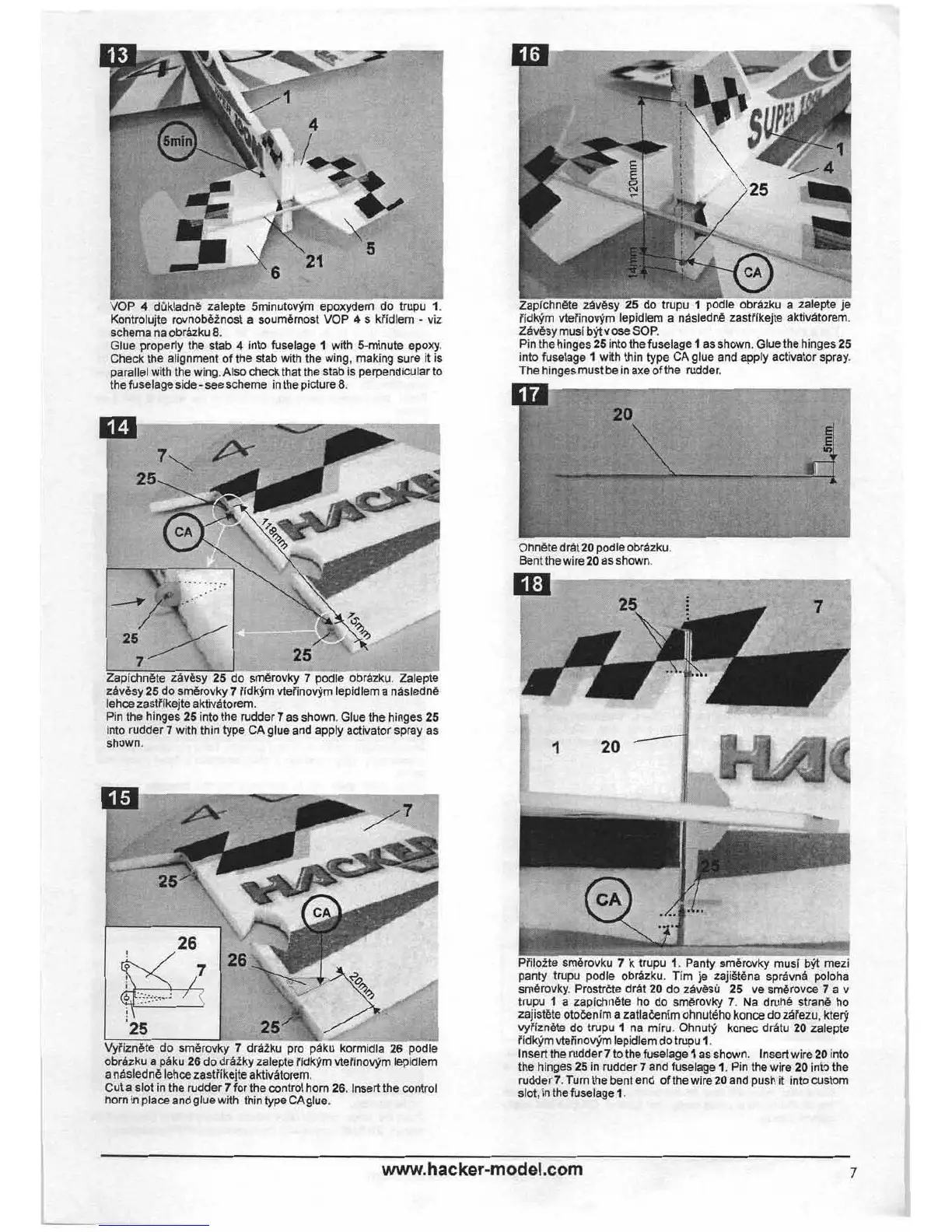
Kontrolujte rovnobeinost a souml;lrnost VOP
4
s kiidlem
-
viz
schema na
obrazku
8.
Gill-
properly the stab
4
into fuselage
1
with 5-minute epoxy.
k the alignment of the stab with the wing, making sure it is
el with the wing. Also check that the stab is perpendicular to
selage side -see scheme in the picture
8.
Pin the hinges
25
into the rudder
7
as shown. Glue the hinges
25
into rudder
7
with thin type CA glue and apply activator spray as
nhnwn
Wiiznete do smerovky
7
draiku pro paku kormidla
26
~odle
obrAzku a psku
26
do drdiky zalepte iidkvm vteiinowm le6dlem
a nasledne lehce zastiikejte aktivatorem.
Cut a slot in the rudder
7
for the control horn
26.
Insert the control
horn in place and
qlue with thin type CAglue.
I
--
,-
iidkym vteiino@m- lepidlem a 'nasledne zastiikejte aktivatorem.
Zavesy musi
bfl v ose SOP.
Pin the hinges
25
into the fuselage
1
as shown. Glue the hinges
25
into fuselage
1
with thin type CA glue and apply activator spray.
The hinges must be in axe of the rudder.
Ohnete
I
Bent the
drat
20
podle obrazku.
I
wire
20
as shown.
panty trupu podle obrazku. Tim
je-zajistena spravna -poloha
smerovky. Prostrete drat
20
do zAv6sG
25
ve smerovce
7
a v
trupu
I
a zapichnete ho do smerovky
7.
Na druhe strang ho
zajistete otoCenim a zatlaknim ohnuteho konce do zaTezu, kte
j
vyiizngte do trupu
1
na miru. Ohnuty konec drfitu 20 zalepte
Tidkym vteiinovym lepidlem do trupu
1.
lnsert the rudder
7
to the fuselage
1
as
shown. lnsert wire
20
into
the hinges
25
in rudder 7 and fuselage
1.
Pin the wire
20
into the
rudder
7.
Turn the bent end of the wire 20 and push it into custom
slot, in the fuselage
I.