Do you have a question about the HAEGER 618 MSPe and is the answer not in the manual?
Contact information for Haeger's global offices and support.
Official declaration of product compliance with EU directives and standards.
Defines the intended operating environment and limitations of the machine.
General safety precautions and warnings for machine operation.
Information on obtaining technical support and repair services.
Outlines the duties and training requirements for machine operators.
Defines the role and qualifications of service personnel.
Emphasizes the importance of high-quality components for performance.
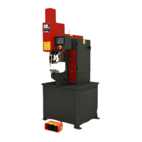
Provides technical specifications and physical dimensions of the machine.
Explains pictograms and signal words used for safety warnings.
Guidelines for safely moving and positioning the machine.
Specifies the optimal area around the machine for safe operation.
Step-by-step instructions for removing the machine from its shipping skids.
Procedures for leveling and positioning the machine on the shop floor.
Instructions for connecting the machine to the main electrical supply.
Overview of essential controls like the touchscreen and E-Stop button.
Explanation of the footswitch operation in different modes.
Procedure to verify the machine's electrical system functionality.
Details on installing and handling the upper tool holder assembly.
Instructions for installing and securing the lower tool holder.
Steps for configuring the machine for conductive material processing.
Steps for configuring the machine for non-conductive material processing.
Lists critical "Never" statements and general safety advice.
Explains the functionality of the Conductive and Non-Conductive modes.
Details the components and principles behind the safety system.
Procedure for safely isolating the machine during maintenance.
Recommends appropriate fire extinguishers for machine use.
Highlights situations to avoid and inherent machine risks.
Step-by-step guide for testing the machine's safety system.
Overview of operating the Haeger machine safely and productively.
Identifies key hardware controls like E-Stop and foot switches.
Explains the primary interface for machine settings and functions.
Access to programs, settings, and diagnostics.
How to load saved operational programs into the machine.
Configuration settings for the automated parts feeding system.
Describes the option for multi-station programming and setup.
Process for saving current machine settings as a program.
Procedure for first-stroke setup using the Tool Protection System.
Details on configuring parameters for individual insertion stations.
Aids in precise hole location for larger parts.
Automates hardware delivery and positioning for increased productivity.
System for delivering hardware during automatic tooling processes.
Allows insertion of 4 different fasteners in a single part handling.
For positive stop cylinders, includes digital readout for setup.
Shuttle system for accommodating studs, standoffs, and nuts.
Adjustable method for maintaining precise stopping point of the cylinder.
Table outlining components, areas, maintenance tasks, and frequencies.
Daily and weekly cleaning and inspection procedures for key components.
Cleaning and maintenance procedures for the Modular Autofeed System.
Cleaning instructions for the flight tubes used with the MAS.
Information on obtaining customized machine schematics and drawings.
Details on contacting Haeger for support and service requests.
Terms and conditions of the limited warranty for the machine and parts.
Diagram and list of parts for the primary machine assembly.
Continuation of the main assembly parts list with item numbers and descriptions.
Illustrated parts list for the hydraulic cylinder subsystem.
Diagram and list of sheet metal components for the machine.
Continuation of the sheet metal parts list.
Parts list and diagram for the machine's pneumatic air supply system.
Illustrated parts for the dual safety sensor system.
Continuation of the dual safety sensor assembly parts list.
Parts breakdown for the upper tool holder.
Parts list for the J-Frame mounting hardware.
Illustrated parts for the standard lower tool holder.
Parts list for the turret insertion tooling.
Diagram and list of components within the electrical cabinet.
Continuation of the electrical cabinet parts list.
Parts breakdown for the Human-Machine Interface (HMI).
Illustrated parts for the hydraulic reservoir subsystem.
Continuation of the hydraulic reservoir assembly parts list.
Parts list for the hydraulic manifold subsystem.
Continuation of the hydraulic manifold subassembly parts list.
Parts breakdown for the hydraulic return filter.
Parts list for the machine's service tray.
Illustrated parts for the MAS-9 Autofeed system.
Continuation of the MAS-9 Autofeed parts list.
Illustrated parts for the MAS 350 Autofeed system.
Continuation of the MAS 350 Autofeed parts list.
Parts list for the optional vacuum generator assembly.
Parts breakdown for the optional positive stop assembly.
| Category | Power Tool |
|---|---|
| Type | Magnetic Drill Press |
| Model | 618 MSPe |
| Voltage | 230 V |
| Magnet Force | 15000 N |
| Frequency | 50/60 Hz |